SMD17E2 SPECIFICATIONS
SMD17E2 User Manual
ADVANCED MICRO CONTROLS INC.
12
The SMD17E2 Family (continued)
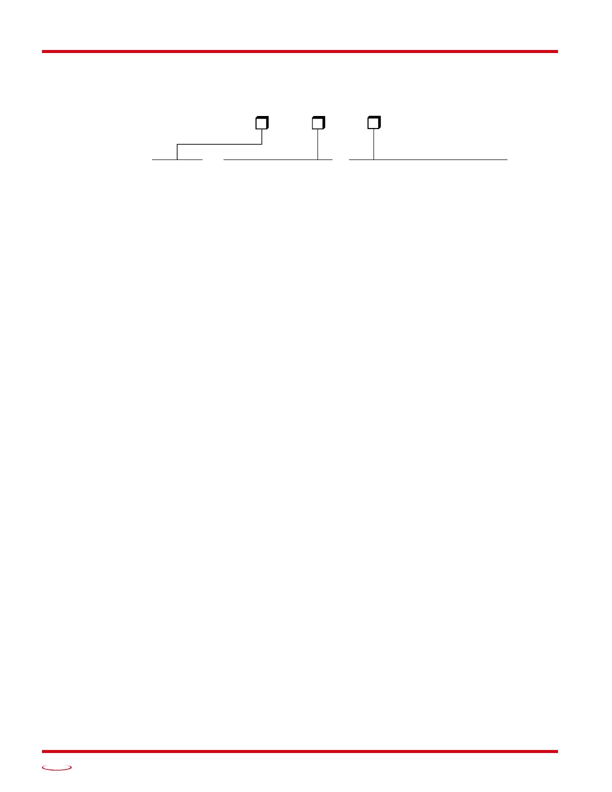
Part Numbering System
Figure R1.2 Part Numbering System
General Functionality
Each member of the SMD17E2 family has three integrated parts:
An indexer that accepts commands over an Ethernet connection using the EtherNet/IP, Modbus TCP, or
PROFINET protocol
A 2.0 Arms micro-stepping driver that accepts 24 to 48 Vdc as its input power source
A high torque size 17 stepper motor (60 or 80 oz-in holding torque).
An incremental or absolute multi-turn encoder is also available for applications that require position feedback
or verification.
The availability of the EtherNet/IP, Modbus TCP, or PROFINET protocols makes the SMD17E2 units easy to
integrate into a wide variety of control systems. This combination of host and driver gives you several advan
-
tages:
Sophisticated I/O processing can be performed in the host (PLC or other controller) before sending
commands to the SMD17E2 unit
All motion logic is programmed in the host, eliminating the need to learn a separate motion control lan-
guage
The integral two port Ethernet switch simplifies network cabling
The DLR interface eliminates single point failures in EtherNet/IP environments
The MRP interface eliminates single point failures in PROFINET environments
The elimination of the separate indexer and driver lowers total system cost.
An SMD17E2 is powered by a nominal 24 to 48 Vdc power source, and can accept surge voltages of up to
60 Vdc without damage. The output motor current is fully programmable from 0.1 Arms to 2.0 Arms which
makes the SMD17E2 suitable to a wide range of applications. In addition to the Motor Current setting,
the Motor Steps per Turn, Idle Current Reduction, and Anti-Resonance Circuit features are also fully pro-
grammable. If you have used other stepper indexer products from AMCI, you will find programming an
SMD17E2 to be very similar to these products.
The SMD17E2 contains a true RMS motor current control driver. This means that you will always receive
the motor’s rated torque regardless of the Motor Steps/Turn setting. (Drivers that control the peak current to
the motor experience a 30% decrease in motor torque when microstepping a motor.) The combination of an
ultra-low inductance motor and a high-power, true RMS driver gives unprecedented torque vs. speed perfor
-
mance for any DC application.
CONNECTOR TYPE
‘-M12’ =
Network: (2) 4 pin Female D-Type
Power: (1) 5 pin Male A-Type
IP50 Rating
M12 Connectors
‘-M12S’ = M12 Connectors, Shaft Seal
Network: (2) 4 pin Female D-Type
Power: (1) 5 pin Male A-Type
IP64 Rating
SMD17E2 –
ENCODER
‘blank’ = No encoder
A = Absolute Multi-turn Encoder
2,048 counts/turn.
E = Incremental Encoder
4,096 counts/turn max.
TORQUE
80 = 80 oz-in
60 = 60 oz-in