20 Gear Drive, Plymouth Ind. Park, Terryville, CT 06786
Tel: (860) 585-1254 Fax: (860) 584-1973 http://www.amci.com
SMD17E2 User Manual
MOTION CONTROL
31
Basic Move Types (continued)
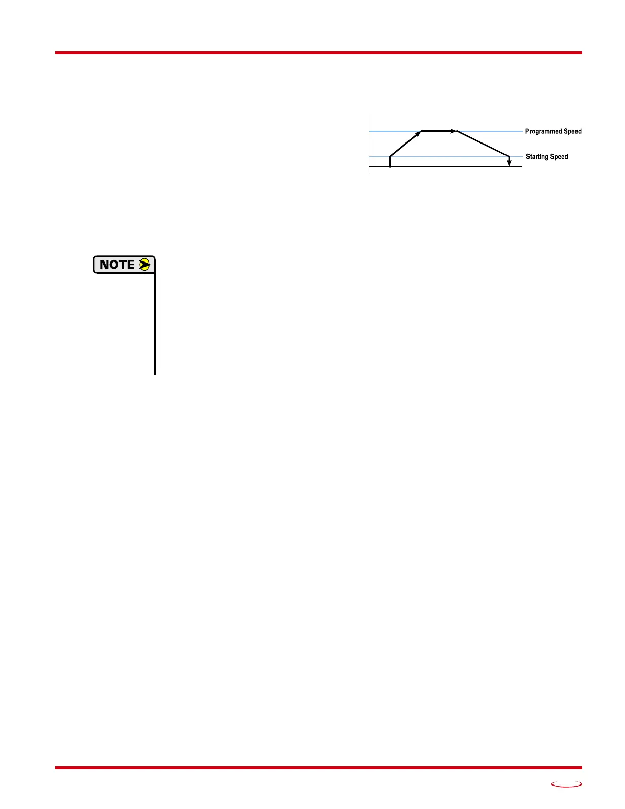
Absolute Move
Absolute Moves move from the Current Position (A)
to a given position (B). (The SMD17E2 calculates the
direction and number of steps needed to move to the
given position and moves that number of steps.) A
trapezoidal profile is shown to the right, but Absolute
Moves can also generate triangular profiles. The com
-
mand’s Target Position can be in the range of
±8,388,607 counts. The move will be clockwise if the
Target Position is greater than the Current Position and
counter-clockwise if the Target Position is less than
the Current Position.
1) The Home Position of the machine must be set before running an Absolute Move. See the
reference section, Homing an SMD17E2, which starts on page 53, for information on hom-
ing the machine.
2) The Motor Position must be valid before you can use an Absolute Move. The Motor Posi-
tion becomes valid when you preset the position or home the machine.
3) Absolute Moves allow you to move your machine without having to calculate relative posi-
tions. If you are controlling a rotary table, you can drive the table to any angle without hav-
ing to calculate the distance to travel. For example an Absolute Move to 180° will move the
table to the correct position regardless of where the move starts from.
Controlled Stop Conditions
The move completes without error.
You toggle the Hold_Move control bit in the Network Output Data. Note that your holding position will
most likely not be the final position you commanded. You can resume a held Absolute Move by using
the Resume_Move bit or the move can be aborted by starting another move. The use of the Hold_Move
and Resume_Move bits is explained in the
Controlling Moves In Progress section starting on page 41.
Immediate Stop Conditions
The Immediate Stop bit makes a 01 transition in the Network Input Data.
An inactive-to-active transition on an input configured as an E-Stop Input.
A CW or CWW Limit Switch is reached. If the limit that is reached is the same as the direction of
travel, for example, hitting the CW limit while running a CW move, a Reset Errors command must be
issued before moves are allowed in that direction again. If the limit that is reached is opposite the direc
-
tion of travel, a Reset Errors command does not have to be issued.
Figure R2.7 Absolute Move
SPEED
B