20 Gear Drive, Plymouth Ind. Park, Terryville, CT 06786
Tel: (860) 585-1254 Fax: (860) 584-1973 http://www.amci.com
SMD17E2 User Manual
IMPLICIT COMMUNICATIONS WITHOUT EDS
111
4.2 Add the SMD17E2 (continued)
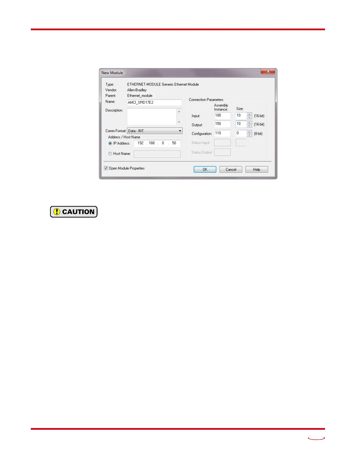
6) Set the following parameters in the Module Properties window. All parameters not listed here are optional.
Figure
T4.3 shows a completed screen.
Figure T4.3 Configuration Screen - Generic Device
Name: A descriptive name for the
SMD17E2
Comm Format: Data - INT
The Comm Format defaults to Data - DINT. The SMD17E2 will not be able to commu-
nicate with the host controller if this format is not changed when the device is added to
the system. Once added, the Comm Format cannot be changed. The device must be
deleted and added to the project if the Comm Format is incorrect.
IP Address: Must be the address you set for the SMD17E2. Refer to the Set the IP Address and Pro-
tocol task chapter starting on page 95 for information on setting the IP Address of the unit.
Input: Assembly Instance = 100, Size = 10 words.
Output: Assembly Instance = 150, Size = 10 words.
Configuration: Assembly Instance = 110, Size = 0
7) Verify that the “Open Module Properties” check box is selected and click on [OK]. The Module Properties
window will open. You can set the RPI time as required for your system in this window. The minimum RPI
time for an SMD17E2 is 2 milliseconds. When done, click on [OK] to complete the setup.
Error Code 16#0109
The PLC will generate an Error Code 16#0109 when the Comm Format parameter is not changed from its
default of “Data-DINT” to “Data-INT”. This is the most common cause of communication failures with the
SMD17E2.
4.3 Configure the SMD17E2
With the configuration assembly instance size set the zero, the device will join the EtherNet/IP network as
soon as the request is made to it. If the SMD17E2 has a configuration stored in flash memory, it will be to
configure the unit on power up. You can also configure the unit at anytime and store this new configuration to
flash. Configuration is accomplished by writing a block of data to the device that is formatted according to the
specifications in the
Configuration Mode Data Format, reference chapter, which starts on page 59.
It is possible to store configuration data in the flash memory of the SMD17E2 and this configuration will be
used on power up to configure the device. However, writing the configuration data to the driver on power up
may simplify system maintenance if the device ever has to be swapped out.