20 Gear Drive, Plymouth Ind. Park, Terryville, CT 06786
Tel: (860) 585-1254 Fax: (860) 584-1973 http://www.amci.com
SMD17E2 User Manual
SMD17E2 SPECIFICATIONS
19
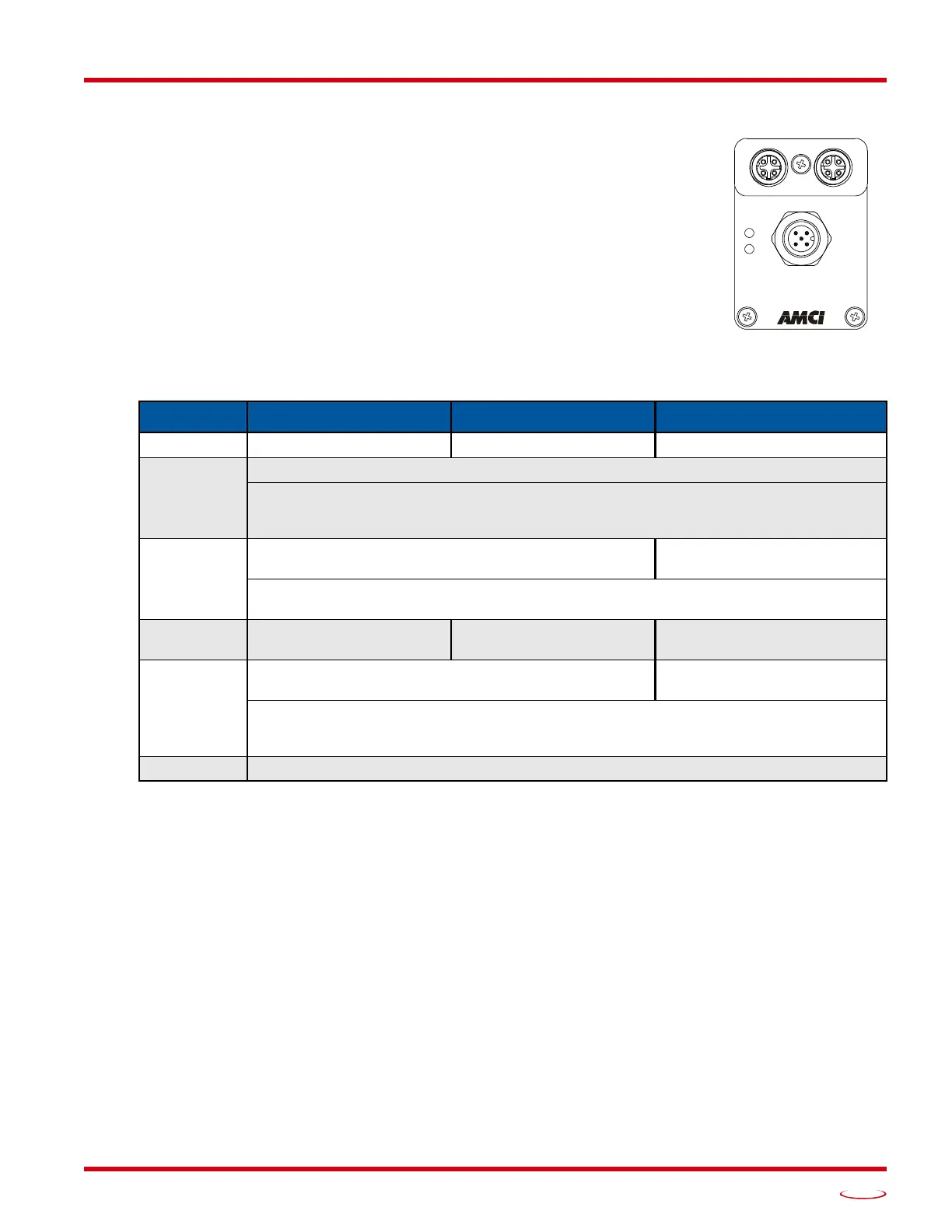
Status LED’s
Each SMD17E2 has two status LED’s that show module and network status. As
shown in figure R1.3, these LED’s are located on the rear cover.
Module Status (MS) LED
The Module Status LED is a bi-color red/gree
n LED. The state of the LED depends
on the state of the network adapter module.
Table R1.3 Module Status LED States
Power Up Behavior
Blinking Green:
The unit will blink the Module Status LED green during initialization.
Blinking Red: The unit will blink the Module Status LED red three times if there is an error with the
internal absolute encoder.
LED State EtherNet/IP Definition Modbus TCP Definition PROFINET Definition
Off No Power No Power No power
Alternating
Red/Green
Initializing: Power up Self-Test
Communications failure. There is a communications error between the main processor and
the ethernet co-processor within the unit. You must cycle power to the SMD17E2 to
attempt to clear this fault.
Flashing
Gree
n
Initializing: Waiting for valid physical
connection to the
network.
Successful write to flash memory. Power must be
cycled to the unit before additional
commands can be written to it.
Steady Green
Drive and Network are
operational.
Drive and Network are
operational.
Device Name or IP Address
are set.
Flashing Red
Initializing: IP Address conflict
Initializing: Device Name or
IP A
ddress are not set.
If the Network Status LED is also flashing, the IP Address or Network Protocol has been
changed. Cycle power to the unit to continue. If the Network Status LED is in any other
state, a write to flash memory has failed. Cycle power to the unit to clear this fault.
Steady Red Overtemperature fault. Remove power from the unit and allow it to cool to clear the fault.
Figure R1.3 Rear Cover
Status LED’s
POWER & INPUTS
Power: 24 to 48 Vdc