INSTALLING THE SMD17E2
SMD17E2 User Manual
ADVANCED MICRO CONTROLS INC.
88
1.3 Mounting (continued)
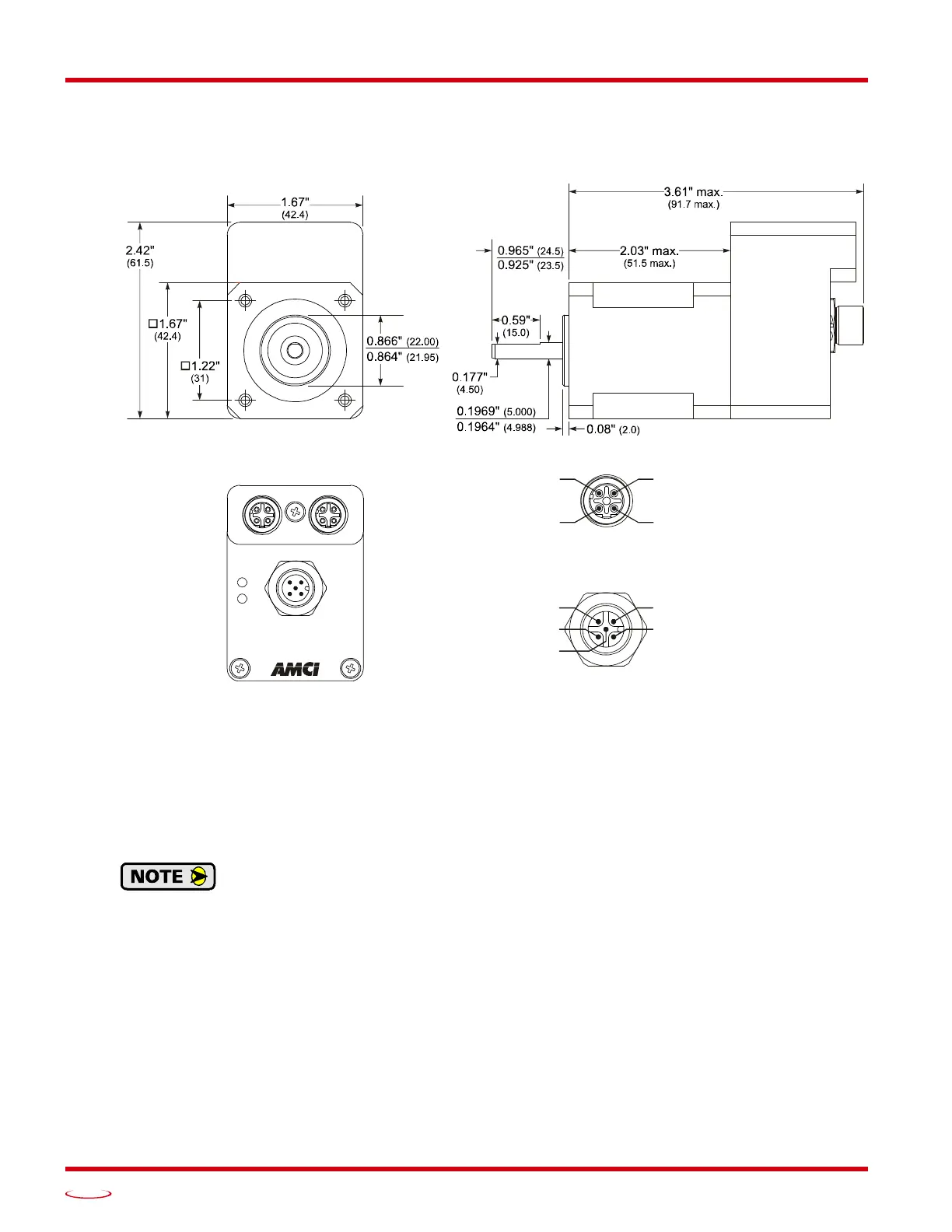
1.3.4 SMD17E2-80 Outline Drawing
Figure T1.2 SMD17E2-80 Outline Drawing
1.3.5 Connecting the Load
Care must be exercised when connecting your load to the stepper motor. Even small shaft misalignments can
cause large loading effects on the bearings of the motor and load. The use of a flexible coupler is strongly rec
-
ommended whenever possible.
Maximum radial load is 6.5 lbs. (29 N) at the center of the flat on the shaft.
Maximum axial load is 5.6 lbs. (25 N)
Internal encoders are mounted on the end of the motor shaft that is internal to the unit. Exces-
sive axial load may cause encoder mis-alignment and damage to the unit. This type of damage
is not covered under warranty.
PORT 2
POWER & INPUTS
MS
NS
PORT 1
Power: 24 to 48 Vdc
Pin 1: +TxPin 2: +Rx
Pin 4: –Rx
Pin 3: –Tx
ETHERNET
Ports 1 & 2
POWER & INPUTS
Pin 1: DCPower
5: DCPower
2: Input 1
3: DC Common
Pin 4: Input 2