20 Gear Drive, Plymouth Ind. Park, Terryville, CT 06786
Tel: (860) 585-1254 Fax: (860) 584-1973 http://www.amci.com
SMD17E2 User Manual
COMMAND MODE DATA FORMAT
81
Input Data Format
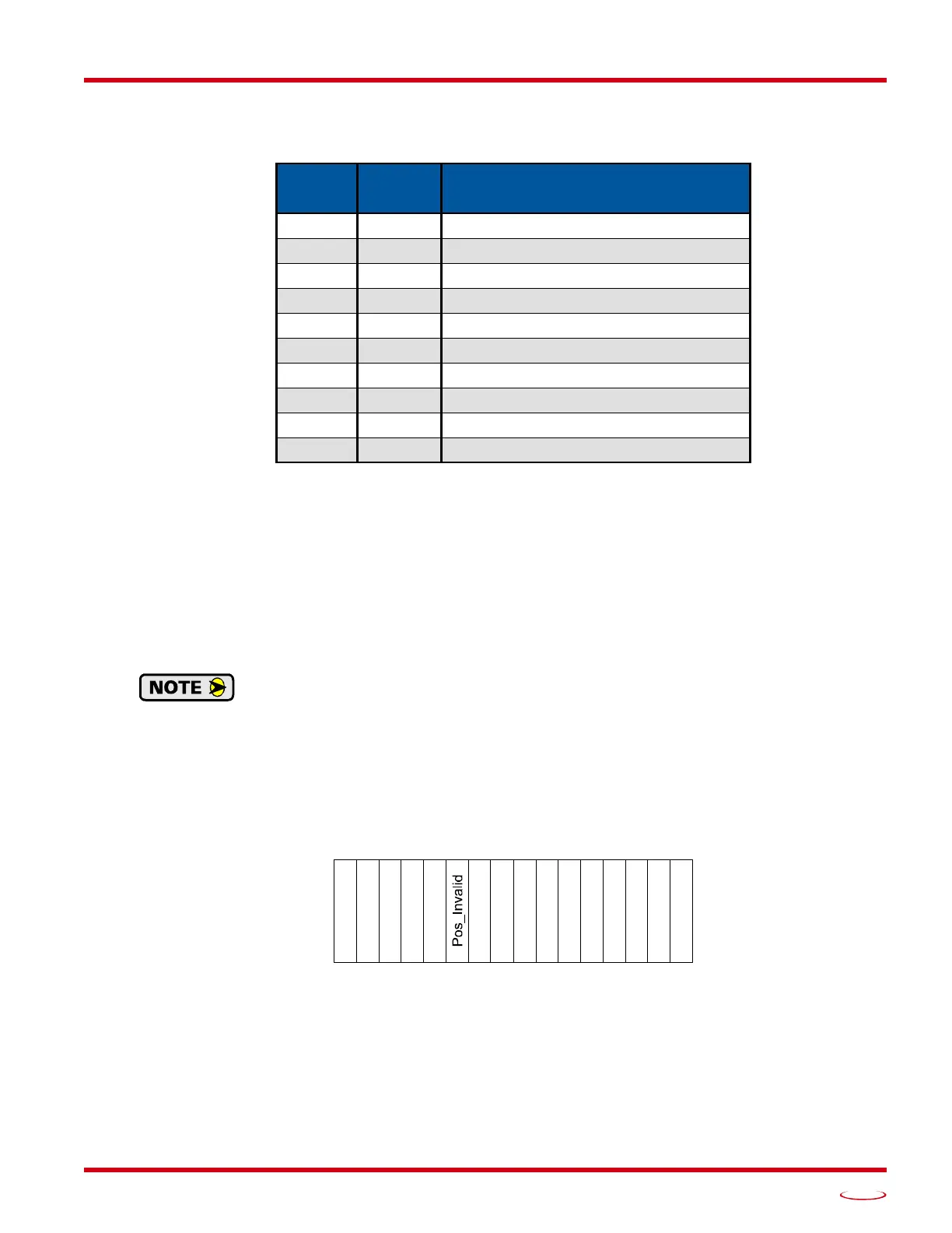
The correct format for the Network Input Data when the SMD17E2 is in Command Mode is shown below.
Table R6.19 Network Input Data Format: Command Mode
Format of Position Data Values
The format of the Motor Position, Encoder Position, and Trapped Encoder Position values is controlled by the
Binary_Input_Format bit in the configuration data written to the Networked Driver. (See
Configuration
Word 1 Format, bit 9 starting on page 63.) When the Binary_Input_Format bit equals “0”, the position values
are reported with the bottom three digits of the value in the lower word (000 - 999) and the remaining digits in
the upper word. See
Data Format on page 67 for an explanation of this format. When the
Binary_Input_Format bit equals “1”, the position values are reported as 32-bit signed integers, with the loca-
tion of the least significant bit determined by the Binary_Endian bit in the Configuration data.
The range of values when using the multi-word format is -32,768,000 to 32,767,999. When
used in continuous rotation applications, such as control of a conveyor belt, it is possible to
overflow these values. When any of the three position values overflow, the value of the associ
-
ated data words will become indeterminate. AMCI strongly suggests using the signed 32-bit
integer format for continuous rotation applications.
Status Word 0 Format
Figure R6.4 Command Mode: Status Word 0 Format
Bit 15: Mode_Flag – Set to “1” if in Configuration Mode, and set to “0” if in Command Mode.
Bit 14: Module_OK – “1” when the SMD17E2 is operating without a fault, “0” when an internal fault con-
dition exists.
EtherNet/IP
Word
Modbus/TCP
Register
Command Mode Input Data
0 0 Status Word 0
1 1 Status Word 1
2 2 Motor Position: Upper Word
3 3 Motor Position: Lower Word
4 4 Encoder Position: Upper Word
5 5 Encoder Position: Lower Word
6 6 Trapped Encoder Position: Upper Word
7 7 Trapped Encoder Position: Lower Word
8 8 Programmed Motor Current (X10)
9 9 Value of Acceleration Jerk Parameter
Status Word 0
15 14 13 12 11 10 09 08 07 06 05 04 03 02 01 00
Module_OK
Config_Err
Command_Err
Input_Err
ait_AssySeg
_Assy_Mode
Move_Cmp
ecelerating
ccelerating
At_Home
Stopped
_Hold_State
oving_CCW
oving_CW