20 Gear Drive, Plymouth Ind. Park, Terryville, CT 06786
Tel: (860) 585-1254 Fax: (860) 584-1973 http://www.amci.com
SMD17E2 User Manual
SMD17E2 SPECIFICATIONS
21
SMD17E2 Connectors (continued)
Input Connector (continued)
There are two power pins. DCPower
MAIN
powers both the control electronics and the motor. DCPower
AUX
powers only the control electronics. Using the DCPower
AUX
pin is optional. If your application requires you
to cut power to your motor under some conditions, using the DCPower
AUX
pin allows you to cut power to
your motor without losing your network connection.
If the unit was ordered with an encoder, the DCPower
AUX
pin will also maintain power to the
encoder. If the motor shaft is rotated while motor power is removed, the encoder position will
update. (The motor position will not update.) Once power is restored to the motor, a Preset
Position command can be issued to restore the correct motor position without having to go
through a homing sequence. If Stall Detection is enabled on the SMD17E2, it will also be able
to tell the system if the motor shaft rotated more than forty-five degrees with power removed.
Ethernet Connectors
Figure R1.4 also show the placement of the sealed Ethernet Connector(s), while figure R1.6 shows the con-
nector pinout when viewed from the back of the SMD17E2. The Ethernet port on the SMD17E2 is an “auto-
sense” port that will automatically switch between 10baseT and 100baseT depending on the network equip
-
ment it is attached to. The port also has “auto switch” capability. This means that a standard cable can be used
when connecting the SMD17E2 to any device, including a personal computer.
Figure R1.6 Ethernet Connector Pinout
The connector is a standard four pin D-coded female M12 connector that is rated to IP67 when the mate is
properly attached.
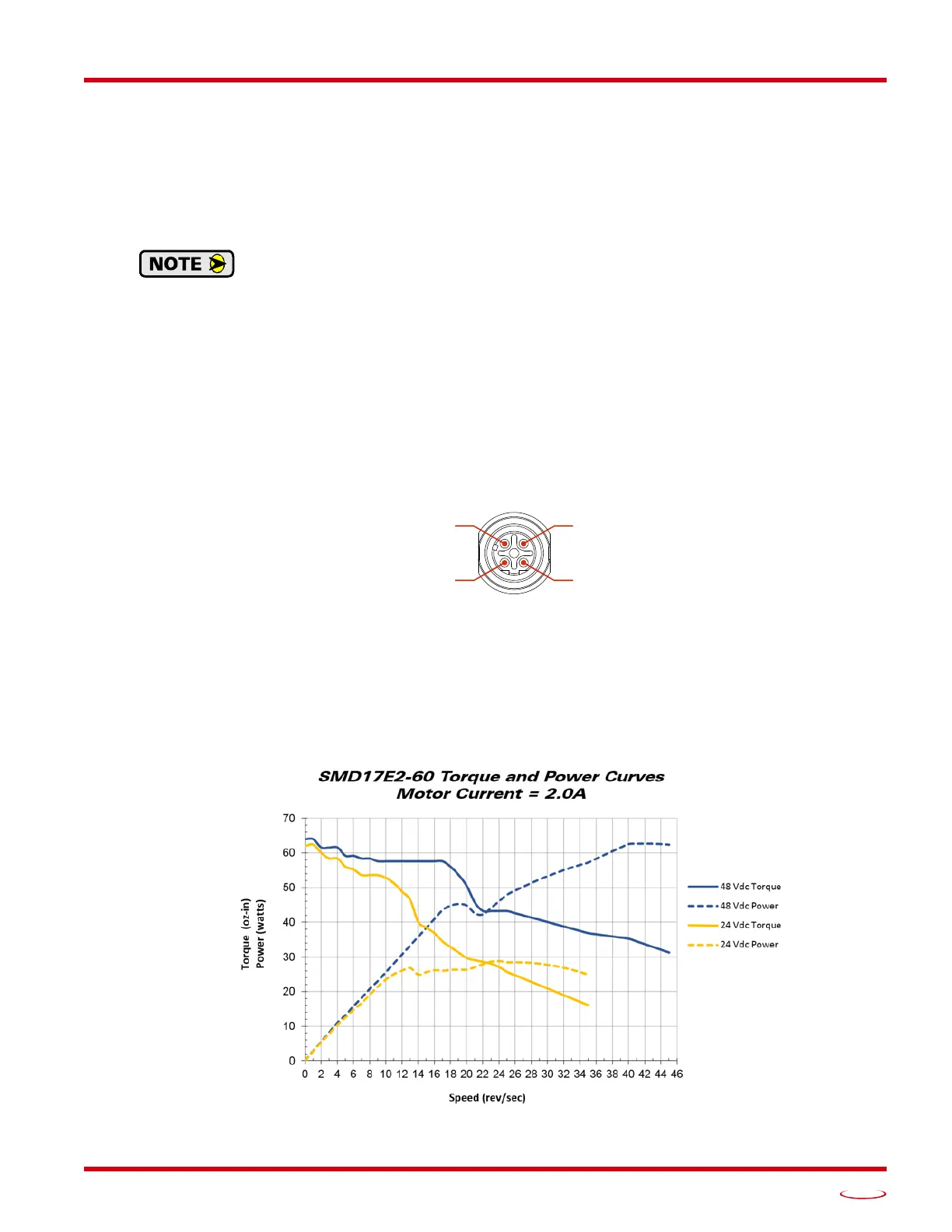
Torque and Power Curves
Figure R1.7 SMD17E2-60 Torque and Power Curves
(Port 1 & Port 2)
Pin 1: +Tx
Pin 4: –Rx