CONFIGURATION MODE DATA FORMAT
SMD17E2 User Manual
ADVANCED MICRO CONTROLS INC.
62
Output Data Format (continued)
Configuration Word 0 Format (continued)
Bit 10: Use_Encoder – “0” when the built-in encoder is not used or not available. “1” to enable the built-in
absolute or quadrature encoder. You must also program the Encoder_Resolution parameter in config
-
uration word 6.
Bits 9-6: Reserved – Must equal “0”.
Bits 5-3: Input 2 Function – See the table below.
Bits 2-0: Input 1 Function – See the table below.
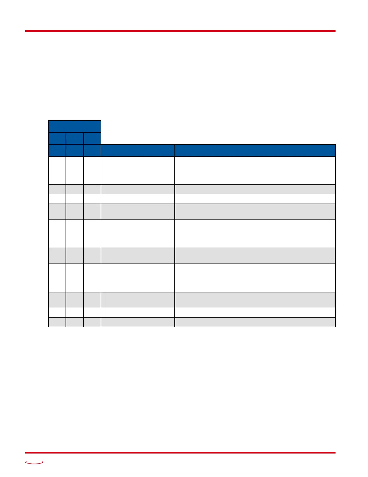
Table R5.4 Configuration Data: Input Function Selections
Bits
5 4 3
2 1 0 Function Available On
0 0 0 General Purpose Input
The input is not used in any of the functions of the
SMD17E2, but it’s status is reported in the Network Data.
This allows the input to be used as a discrete DC input to
the host controller.
0 0 1 CW Limit Input defines the mechanical end point for CW motion.
0 1 0 CCW Limit Input defines the mechanical end point for CCW motion.
0 1 1 Start Indexed Move
Starts the move that is currently located in the output reg-
isters.
0 1 1
Start Indexed Move /
Capture Encoder Value
When the encoder is enabled on an SMD17E2, the
encoder position value is captured whenever this input
transitions. An inactive-to-active state transition will also
trigger an Indexed Move if one is pending in the unit.
1 0 0
Stop Jog or
Registration Move
Brings a Jog or Registration Move to a controlled stop.
1 0 0
Stop Jog or
Registration Move
&
Capture Encoder Value
When the encoder is enabled on an SMD17E2, the
encoder position value is captured when the input triggers
a controlled stop to a Jog or Registration move.
1 0 1 Emergency Stop
All motion is immediately stopped when this input makes
an inactive-to-active transition.
1 1 0 Home Used to define the home position of the machine.
1 1 1 Invalid Combination This bit combination is reserved.