20 Gear Drive, Plymouth Ind. Park, Terryville, CT 06786
Tel: (860) 585-1254 Fax: (860) 584-1973 http://www.amci.com
SMD17E2 User Manual
MOTION CONTROL
37
Assembled Moves (continued)
Dwell Move (continued)
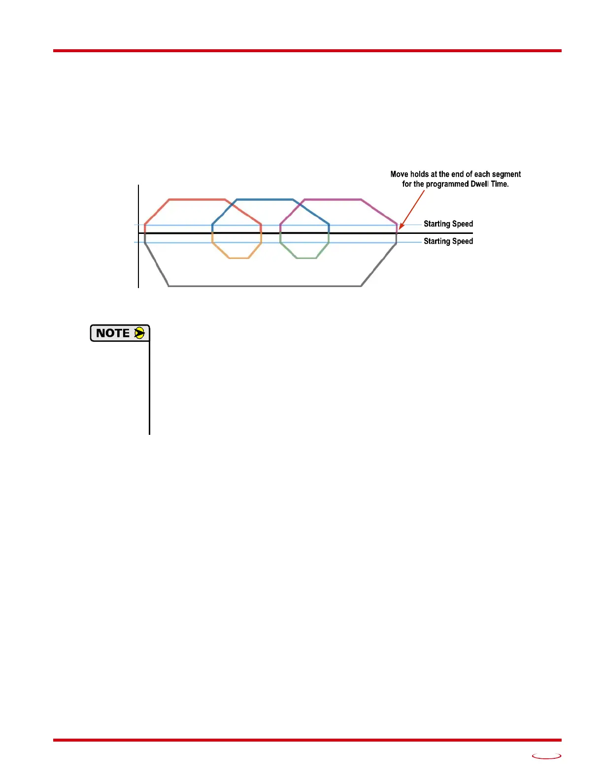
The following figure shows a drilling profile that enters the part in stages and reverses direction during the drill-
ing operation so chips can be relieved from the bit. You
could
accomplish this Dwell Move with a series of six
relative moves that are sent down to the
SMD17E2 s
equentially. The two advantages of a Dwell Move in this
case are that the
unit
will be more accurate with the Dwell Time then you can be in your control program, and
Dwell Moves simplify your program’s logic.
Figure R2.12 Dwell Move
1) You do not have to preset the position or home the machine before you using a Dwell Move.
Because the Dwell Move is based on Relative Moves, it can be run from any location.
2) The Dwell Move is stored in the internal memory of the
SMD17E2
and can be run multiple
times once it is written to the unit. The Dwell Move data stays in memory until power is
removed, the unit is sent new Configuration Data, or a new Blend or Dwell Move is written to
the
unit
. As described in
Saving an Assembled Move in Flash
on page 38, it is also possible
to save a Dwell Move to flash memory. This move is restored on power up and can be run as
soon as you configure your
SMD17E2
and enter Command Mode.
Controlled Stop Conditions
The move completes without error.
You toggle the Hold_Move control bit in the Network Output Data. When this occurs, the SMD17E2
decelerates the move at the deceleration rate of the present segment to the Starting Speed and ends the
move. Note that your final position will most likely not be the one you commanded. A Dwell Move that
is brought to a controlled stop with the Hold_Move bit cannot be restarted.
Immediate Stop Conditions
The Immediate_Stop bit makes a 01 transition in the Network Input Data.
A positive transition on an input configured as an E-Stop Input.
A CW or CWW Limit Switch is reached. If the limit that is reached is the same as the direction of
travel, for example, hitting the CW limit while running a CW move, a Reset Errors command must be
issued before moves are allowed in that direction again. If the limit that is reached is opposite the direc
-
tion of travel, a Reset Errors command does not have to be issued.
SPEED
POSITION
Segment 2
Segment 4
Segment 6
Segment 3 Segment 5