xi IXM User Manual
List of Figures
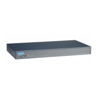
Figure 2.1 Front View ..................................................................................................................... 6
Figure 2.2 Front View ..................................................................................................................... 6
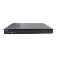
Figure 2.3 Rear View...................................................................................................................... 6
Figure 2.4 Rear View...................................................................................................................... 7
Figure 2.5 Rear View...................................................................................................................... 7
Figure 2.6 Rear View...................................................................................................................... 7
Figure 2.7 System LED Panel ........................................................................................................8
Figure 2.8 System LED Panel ........................................................................................................8
Figure 2.9 EKI-1526/EKI-1526I Dimensions................................................................................... 9
Figure 2.10 EKI-1528/EKI-1528I Dimensions................................................................................. 10
Figure 2.11 EKI-1526T/EKI-1526TI Dimensions ............................................................................ 11
Figure 2.12 EKI-1528T/EKI-1528TI Dimensions ............................................................................ 12
Figure 2.13 Installing the Rack Mount Brackets ............................................................................. 13
Figure 2.14 Installing the Switch..................................................................................................... 13
Figure 2.15 DB9 Pin Assignment....................................................................................................13
Figure 2.16 Connecting AC Power ................................................................................................. 14
Figure 2.17 Connecting DC Power................................................................................................. 14
Figure 3.1 InstallShield Wizard 1 of 4...........................................................................................17
Figure 3.2 InstallShield Wizard 2 of 4...........................................................................................17
Figure 3.3 InstallShield Wizard 3 of 4...........................................................................................18
Figure 3.4 InstallShield Wizard 4 of 4...........................................................................................18
Figure 3.5 Configuration Utility Overview ..................................................................................... 19
Figure 3.6 Quick Tool Bar Overview............................................................................................. 20
Figure 3.7 View > Settings > Main Form Setting .......................................................................... 21
Figure 3.8 View > Settings > Device Manager ............................................................................. 22
Figure 3.9 Open View of Serial Device Configuration Utility......................................................... 23
Figure 3.10 Selecting a Group........................................................................................................ 24
Figure 3.11 Selecting a Device....................................................................................................... 24
Figure 3.12 Viewing Basic Settings ................................................................................................ 25
Figure 3.13 Network Settings Overview ......................................................................................... 26
Figure 3.14 Reset Device ............................................................................................................... 27
Figure 3.15 Locate the Serial Device Server.................................................................................. 28
Figure 3.16 Lock the Serial Device Server ..................................................................................... 29
Figure 3.17 Enter a Password ........................................................................................................29
Figure 3.18 Reset Device ............................................................................................................... 30
Figure 3.19 Unlock the Serial Device Server.................................................................................. 31
Figure 3.20 Change Password ....................................................................................................... 32
Figure 3.21 Update Firmware......................................................................................................... 33
Figure 4.1 Virtual COM Mode....................................................................................................... 35
Figure 4.2 Configuring Virtual COM Mode.................................................................................... 36
Figure 4.3 USDG TCP Client Mode.............................................................................................. 37
Figure 4.4 Peer for Receiving Data .............................................................................................. 38
Figure 4.5 USDG TCP Server Mode ............................................................................................ 38
Figure 4.6 USDG Data Mode........................................................................................................38
Figure 4.7 USDG Control Mode.................................................................................................... 40
Figure 5.1 Selecting Auto Mapping............................................................................................... 43
Figure 5.2 Selecting Auto Mapping............................................................................................... 44
Figure 5.3 Mapping Selected Ports .............................................................................................. 44
Figure 5.4 Viewing VCOM Mapping Results ................................................................................ 44
Figure 5.5 Selecting Manual Mapping .......................................................................................... 45
Figure 5.6 Selecting Manual Mapping .......................................................................................... 45
Figure 5.7 Viewing Manual VCOM Mapping Results.................................................................... 46
Figure 5.8 Selecting the Configuration Wizard ............................................................................. 46
Figure 5.9 Serial Port Listing on EKI Device................................................................................. 47
Figure 5.10 System Port VCOM Mapping Configuration................................................................ 48
Figure 5.11 Verifying VCOM Mapping Configuration...................................................................... 48