Chapter 4 Angular Measurements
Angular Position Measurements
4-52 Measurements Reference Guide
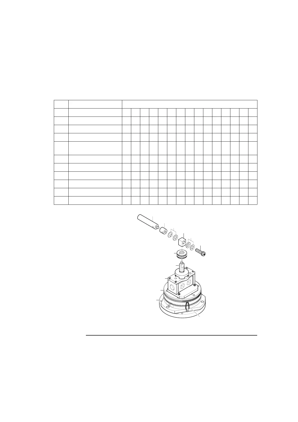
Figure 4-27. Control linkage for horizontal spindle axis and vertical table axis
Ref Description Procedure step number
1 Post 5 7 8 9 12 13 14
2 Post-stub 6789 13
3 Spherical washers 13
4 Adapter 3 7 8 9 13
5 Socket-head cap screw,
M10 x 40 mm
13
6 Clutch breakaway nut 2 11 15
7 Clutch control shaft 2 3 4 7 10 11 15
8 Fixture
9 Precision index table
10 Adapter plate
11 Locking loop(s) 16
1
10
20
30
0
40
50
60
70
80
90
100
110
120
350
340
330
2
4
3
5
6
7
8
9
10
3
11
 Loading...


