Chapter 5 Straightness Measurements
Mounting and Aligning Optics for X-Axis or Y-Axis Measurements
Measurements Reference Guide 5-13
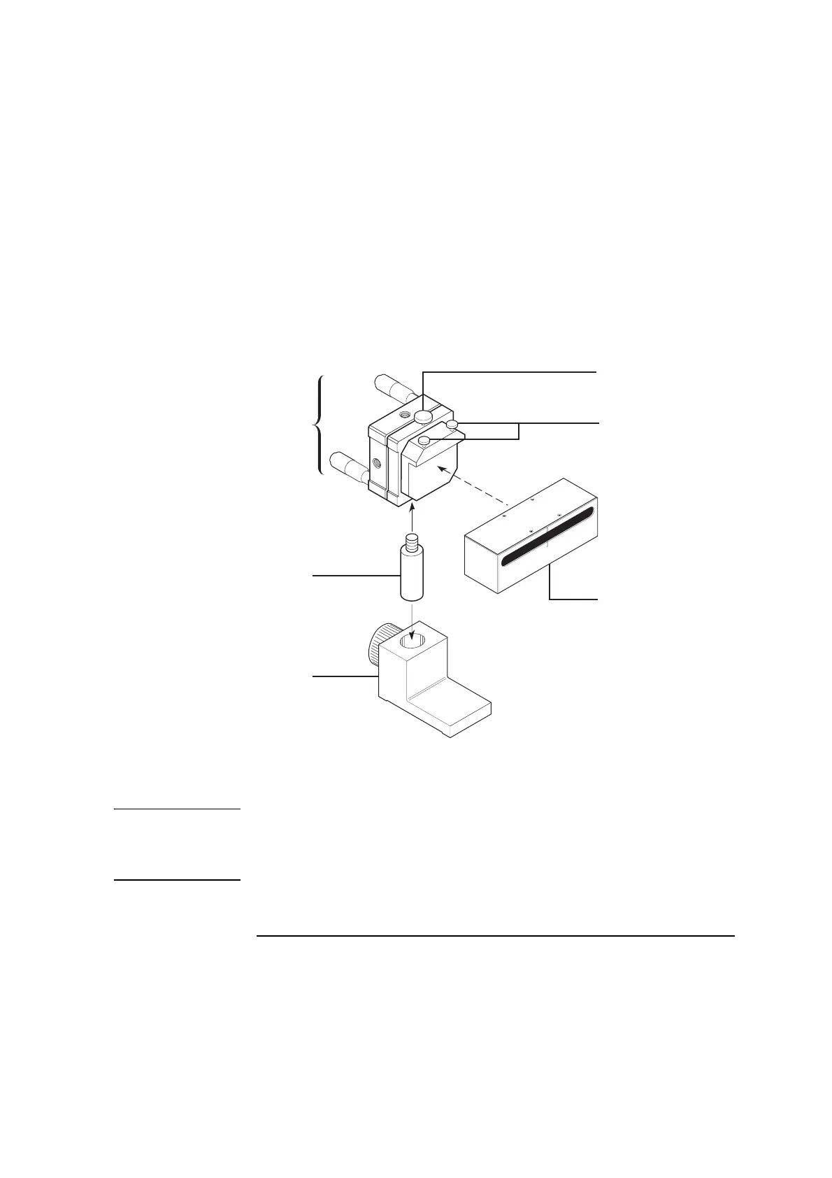
4 Assemble the reflector and its mounting hardware as shown in Figure 5-8.
Position the reflector so the slot is closest to the top edge.
Figure 5-8. Assembling the reflector assembly for horizontal measurements
NOTE If you will be making a linear or angular measurement after the
straightness measurement, position the reflector as low as possible on its
base without covering up the hole in the post. Also, position the laser head
so its beam strikes the center of the slot on the reflector.
1
Reflector mount
2 Reflector rotation screw
3 Reflector attachment
screws
4 Reflector
5 Reflector post
6 Reflector base
1
3
4
5
6
2
 Loading...


