Chapter 6 Squareness Measurements in a Horizontal Plane
Mounting and Aligning the Optical Square and Interferometer for the
First Axis Measurement
Measurements Reference Guide 6-13
4 Attach the target to the interferometer on the side facing the laser head.
Make sure that the edges of the target line up as evenly as possible with
the edges of the interferometer’s bezel (Figure 5-9).
5 Rotate the interferometer’s bezel so the scribe line is perpendicular to the
reflector’s slot.
Two beams now exit the interferometer in a plane perpendicular to the
optical square’s slot. If you cannot see the beams, hold a piece of paper in
front of the optical square.
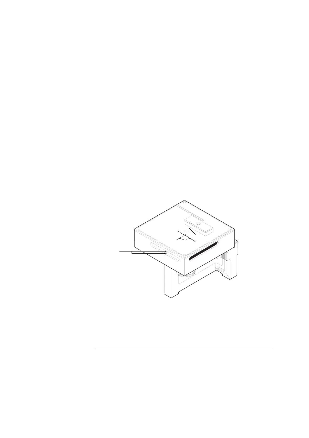
6 Move the optical square back and forth or side to side until the dots are
centered between the midpoint notches on the optical square’s surface
(Figure 6-7).
Figure 6-7. Initial position of the dots on the optical square
7 Secure the optical square to the target machine using a clamp or similar
device so that it is perpendicular to the beam from the laser head.
1
Two dots
90
OPTI
CA
L SQ
UA
R
E
10777A
H
EW
LETT-
P
ACKARD
90
90
1
 Loading...


