Chapter 6 Squareness Measurements in a Horizontal Plane
Mounting and Aligning Optics for the Second Axis Measurement
Measurements Reference Guide 6-25
• If your machine has a horizontal spindle, you assemble and mount the
interferometer assembly horizontally as shown in Figure 6-13 instead
of vertically as specified in Chapter 5. Even though the alignment
procedures in Chapter 5 are for machines with a vertical spindle, you
can still use them to align the optics on your machine.
• If your machine has a vertical spindle, ignore instructions in
Chapter 5 for assembling and mounting the interferometer since you
have already done so. Instead, move the spindle so it is between the
laser head and the reflector, and go directly to “Aligning the optics” in
“Mounting and Aligning Optics for X-Axis or Y-Axis Measurements” in
Chapter 5.
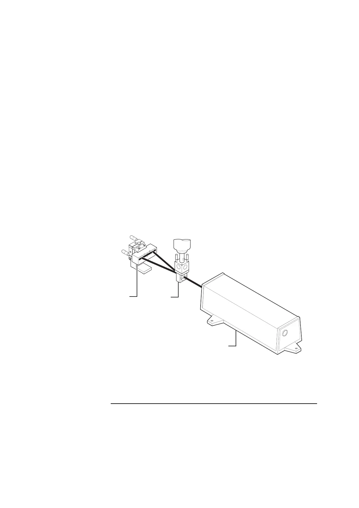
Figure 6-12. Second axis positioning of optics on a machine with a
vertical spindle
1
Reflector oriented
horizontally
2 Interferometer mounted
in a spindle
3 Laser head
1
2
3
1A
 Loading...


