Chapter 7 Squareness Measurements in a Vertical Plane
Mounting and Aligning Optics for the Second Axis Measurement
Measurements Reference Guide 7-15
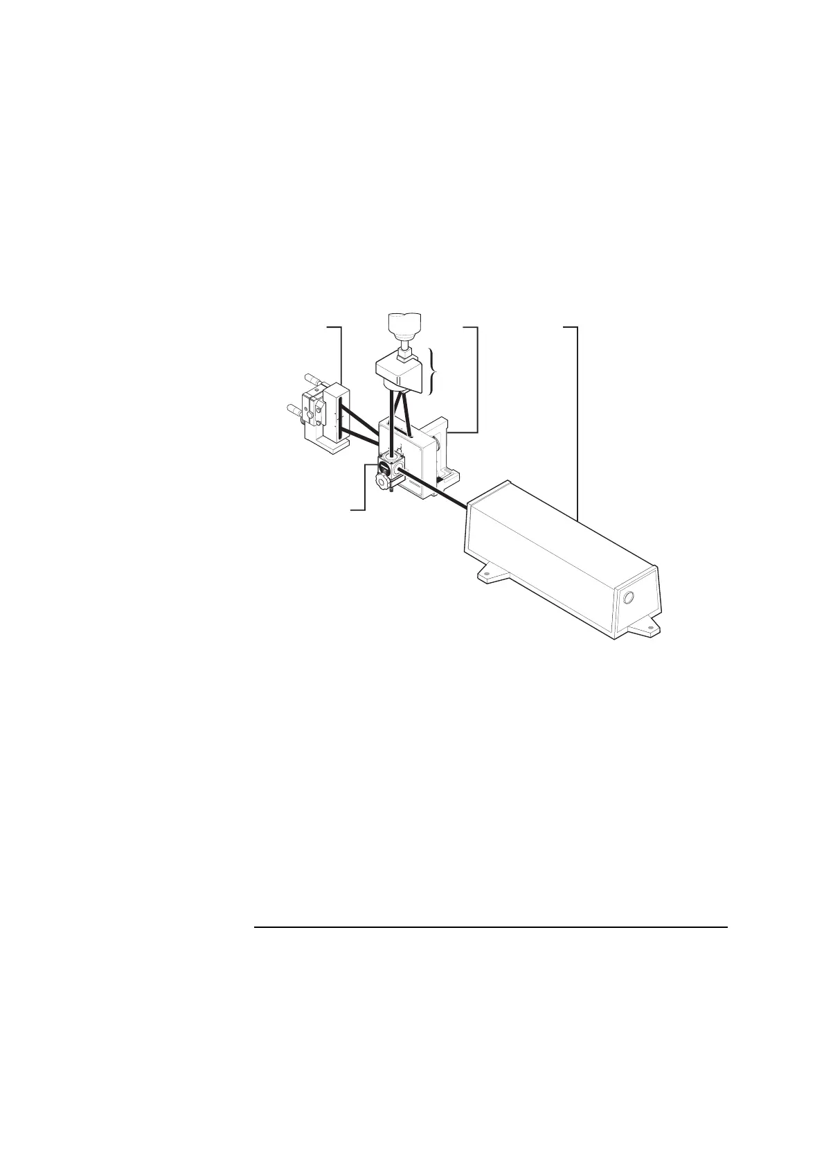
Figure 7-8. Second axis positioning of optics
5 Place the optical square vertically on the machine near the reflector
(Figure 7-8).
Make sure that one of the optical square’s slots points toward the laser
head and the other slot points up.
6 If your machine has T slots that run along the machine’s travel path,
place the optical square so its side is parallel to one of the T slots.
To do this, place two base plates (p/n 10782A) against the edge of a slot
and butt the optical square’s mount against the base plates. This ensures
that the optical square is parallel to the machine’s travel path.
1
Retroreflector oriented
vertically
2 Interferometer assembly
mounted in a spindle
3 Optical square oriented
vertically
4 Laser head
5 Turning mirror
3
1
4
5
2
OPTI
CA
L
SQ
UAR
E
1
0777
A
H
E
W
L
ET
T
-P
A
C
KA
R
D
9
0
1
0
7
7
2
A
T
U
R
N
I
N
G
M
I
R
R
O
R
H
E
W
L
E
T
T
-
P
A
C
K
A
R
D
1
A
1
0
7
72
-
6
7
0
0
2
A
S
S
Y
1A