Chapter 7 Squareness Measurements in a Vertical Plane
Mounting and Aligning Optics for the Second Axis Measurement
Measurements Reference Guide 7-21
15 Using the adjusting screws on the turning mirror’s base (Figure 5-14),
orient the mirror so that the reflected beam enters the upper port on the
laser head.
16 If you cannot get the return beam to enter the upper port, follow these
steps:
a. Remove the gauge block.
b. Attach the interferometer to the retroreflector.
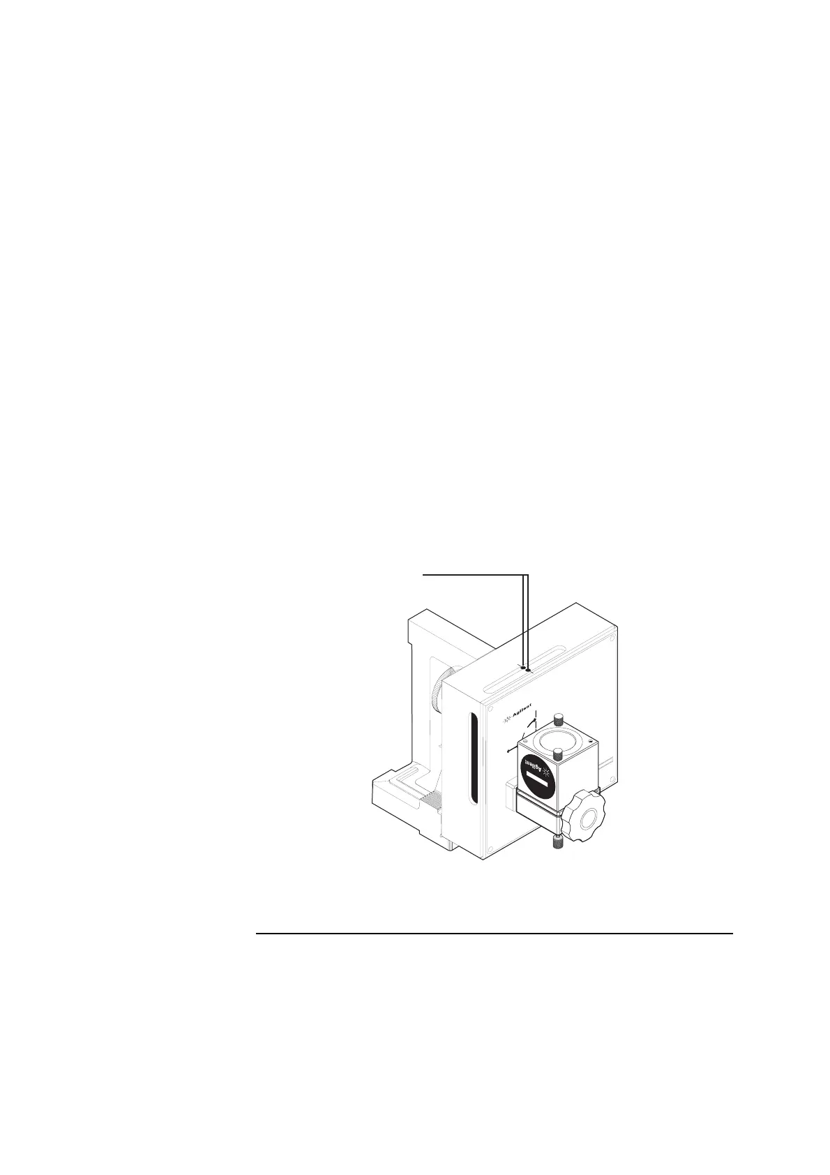
c. Rotate the interferometer’s bezel (Figure 5-9) so the scribe line is
perpendicular to the optical square’s slot.
d. Translate the laser head horizontally and vertically until the two dots
are centered between the midpoint notches on the optical square’s slot
(Figure 7-11).
Figure 7-11. Initial position of the dots on the optical square
1
Two dots
90
OPTI
CA
L SQ
UA
R
E
10777A
90
90
1
0
7
7
2
A
T
U
R
N
I
N
G
M
I
R
R
O
R
1A
10
7
72
-6
70
0
2AS
S
Y
1
 Loading...


