Routine Maintenance: Inlets
Maintaining a split/splitless inlet
Released: March 2004 6850 Series II GC User Information page 125 of 256
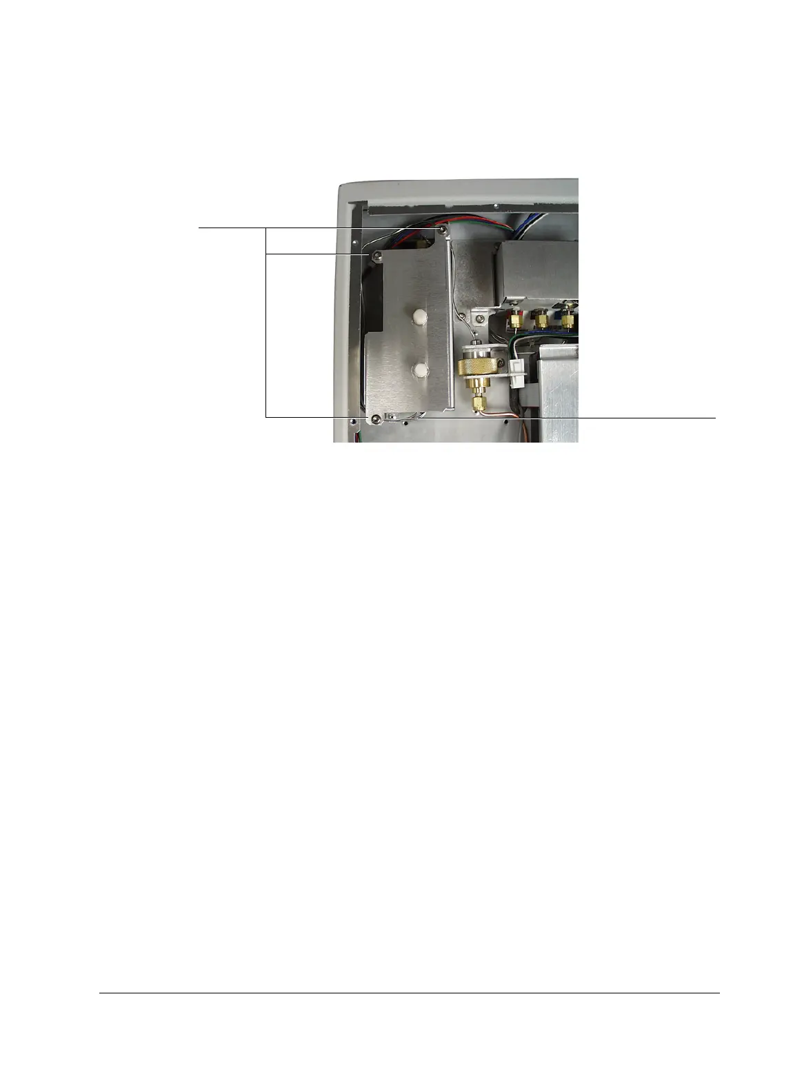
8. Remove the three screws that hold the inlet flow module in the lid.
9. If your 6850 has a valve box installed, remove the valve box cover.
10. Lift the inlet flow module out and remove the manifold block fitting from
the front of the module.
11. Remove the inlet flow module from the instrument.
To install the flow module
1. Use a lint free cloth to clean the surface of the manifold fitting O-rings so
they will make a good compression seal.
2. Lower the inlet flow module into position and install the manifold block
fitting and O-rings.
3. Reconnect the module ribbon cable to the jumper cable.
4. Secure the inlet flow module in place by tightening the three screws.
5. Slide the cover plate in place and tighten the two mounting screws.
6. Reconnect the gas inlet fitting.
7. Check for leaks. See “Leak testing the split/splitless inlet” on page 128 or
refer to your G2629A Control Module documentation for an automatic
test.
Remove
Manifold block fitting

 Loading...


