Introduction
Gas connections
Released: March 2004 6850 Series II GC User Information page 16 of 256
Column oven and column
Use a Control Module or ChemStation/Cerity Chemical to program up to six
temperature ramps, separated by hold periods.
To control the behavior of the carrier gas in the column, specify constant or
ramped flow, or constant or ramped pressure. The GC maintains this behavior
for the entire run, even with temperature programming. The flow modes are
available only if the column is defined.
Automation
Use a Control Module or ChemStation/Cerity Chemical to:
• Set injector control parameters (sample size, syringe size, number of
sample pumps, and other injection parameters)
•Build a run table to execute commands at specified times after injection
•Build a clock table to execute commands at specified times of day
• Create a sequence to analyze a set of samples (vials or stream selection
valve positions) by the active method
• Inject using a gas or liquid sampling valve
• Control a multiposition stream selection valve
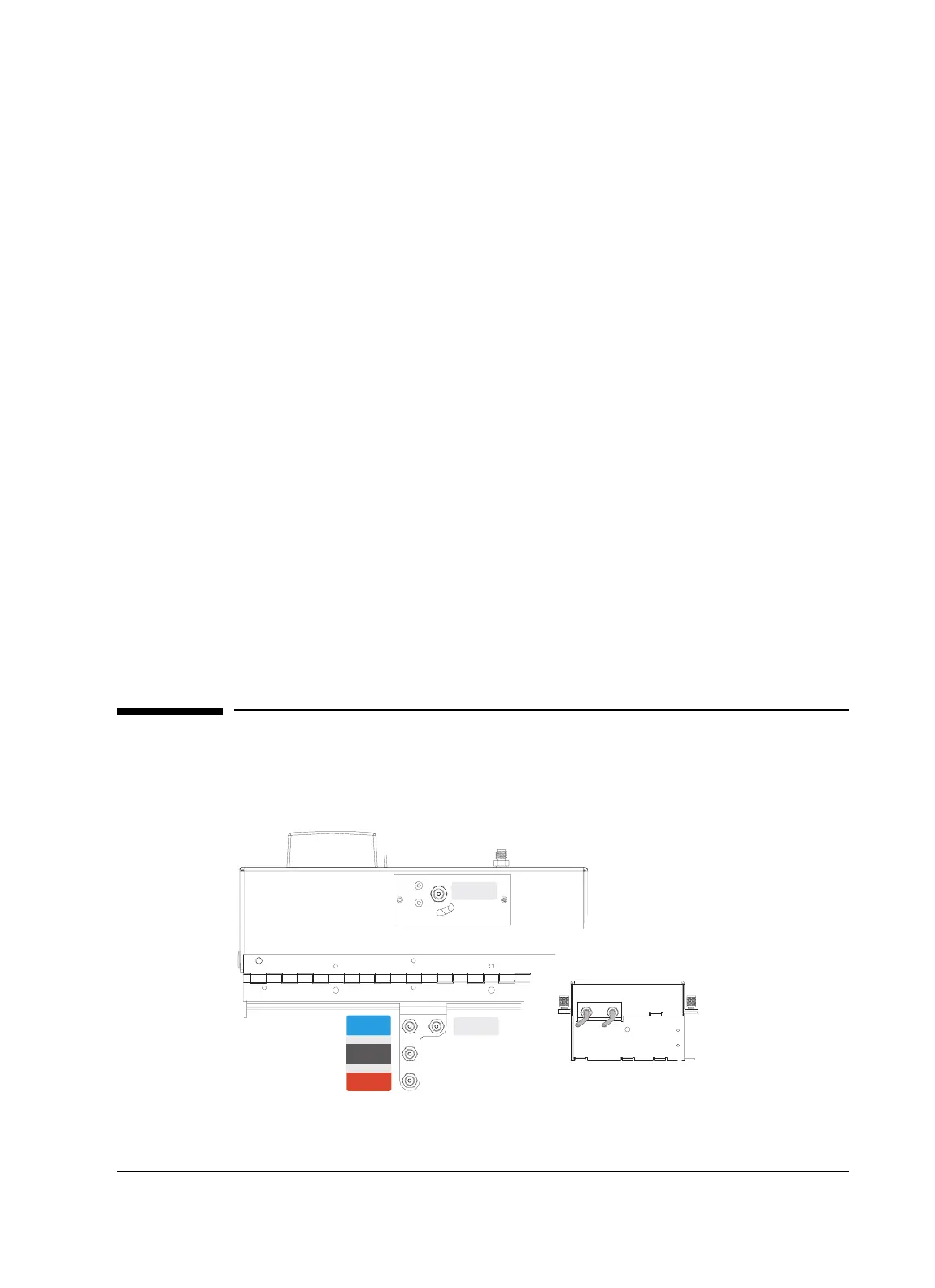
Gas connections
All gas connections are made on the mainframe and lid back panels as shown
in Figure 2.
Figure 2. Gas connections
Actuator
Air
Carrier
Gas
Detector
Air
Reference/
Make-up
Gas
Detector
H2
SAMPLE
OUT
SAMPLE
IN

 Loading...


