Routine Maintenance: General
Maintaining the auxiliary EPC module
Released: March 2004 6850 Series II GC User Information page 116 of 256
Maintaining the auxiliary EPC module
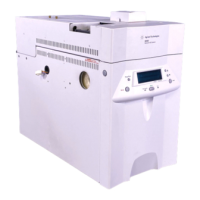
The optional auxiliary EPC module provides three additional auxiliary
pressure control channels. To work properly, there must be adequate flow
resistance downstream of each channel’s pressure sensor. The auxiliary EPC
module provides this restriction for each channel via 3 frit-type restrictors
located in the manifold block on the EPC module exterior.
Four frits are available. A colored dot distinguishes the different types from
each other.
Agilent ships the Red Dot frit in all three channels of a new auxiliary EPC
module.
Select and install frits based on the gas type and flow requirements for the
application. Figure 23 and Figure 24 show approximate pressure/flow
relationships for the three Dot frits, assuming there is no significant additional
resistance downstream of the frits. After changing the type of gas used with the
auxiliary EPC module, check these tables to verify the installed frit types.
Change the frits if needed.
If using a Zero resistance frit, the user must provide flow resistance
downstream and generate the pressure/flow relationships.
Warning When hydrogen is used, dangerously high flows are possible if insufficient flow
resistance is provided downstream of the supply tube. Always use either the
High (Blue Dot) or Medium (Red Dot) frit with hydrogen.
Frit marking Flow resistance Part no.
Blue Dot High 19234-60660
Red Dot Medium 19231-60770
Brown Dot Low 19231-60610
None (brass tube) Zero G1570-20540
 Loading...
