Installation
Configuration
Released: March 2004 6850 Series II GC User Information page 252 of 256
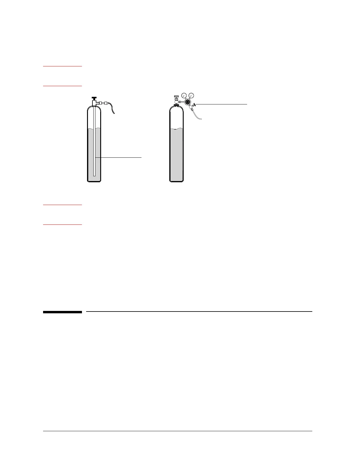
Caution Do not install a pressure regulator on the CO
2
tank, as vaporization and cooling
would occur in the regulator instead of the oven.
Warning All fittings and tubing should be stainless steel. The pressure inside a liquid
CO
2
tank can be as high as 1000 psi.
1. Connect a CGA 320 to 1/4-inch male NPT fitting to the tank followed by a
Swagelok part no. SS-200-7-4 1/4-inch female NPT to 1/8-inch tube fitting.
2. Connect the tank to the cryogenic filter inlet with 1/8-inch diameter heavy-
wall stainless steel tubing. The tubing may be up to 50 feet long.
Allow some slack in the line to make movement of the tank or GC easier.
Coil and fasten the ends of the tubing to keep it from “whipping” if it
breaks.
Configuration
In order to properly control instrument gas flows and temperatures, and to
provide proper functionality for valves, the instrument maintains a list of
manually-configured settings. These include carrier and detector gas types,
valve types (if installed), and the time and date. Agilent sets these parameters
at the factory. In general, if using the same gases as used for the detector
checkout method, no further configuration is needed.
Dip tube
Correct Incorrect
Pressure regulator

 Loading...


