Columns and Traps
Installing capillary columns
Released: March 2004 6850 Series II GC User Information page 38 of 256
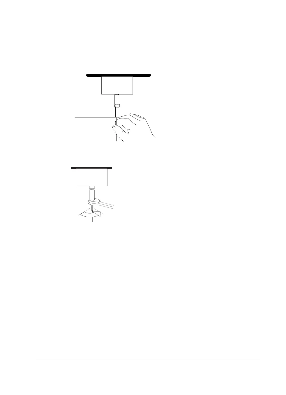
4. Adjust the column position so that the mark on the column is even with
the bottom of the column nut.
5. Tighten the column nut an additional 1/4 to 1/2 turn beyond finger tight so
that the column cannot be pulled from the fitting with gentle pressure.
Installing columns in the purged packed inlet
Agilent Technologies recommends that you avoid using capillary PLOT col-
umns with a purged packed inlet with a gas sampling valve unless you plumb
the valve directly to the column, bypassing the inlet.
Before installing a column in this inlet, be sure you have a capillary liner and
glass insert installed. See “Installing a liner” on page 137 and “Installing a glass
insert” on page 138. If your insulation cup is not installed, begin with Step 1.
Otherwise, begin with Step 4.
Correction fluid mark
1/4 turn

 Loading...


