44 Agilent 8453 Dissolution Testing System Installing and Operating Manual
2Setting Up
Installing a Valve-based Sampling System
Connecting Cables
Check you have the cables shown in Table 12.
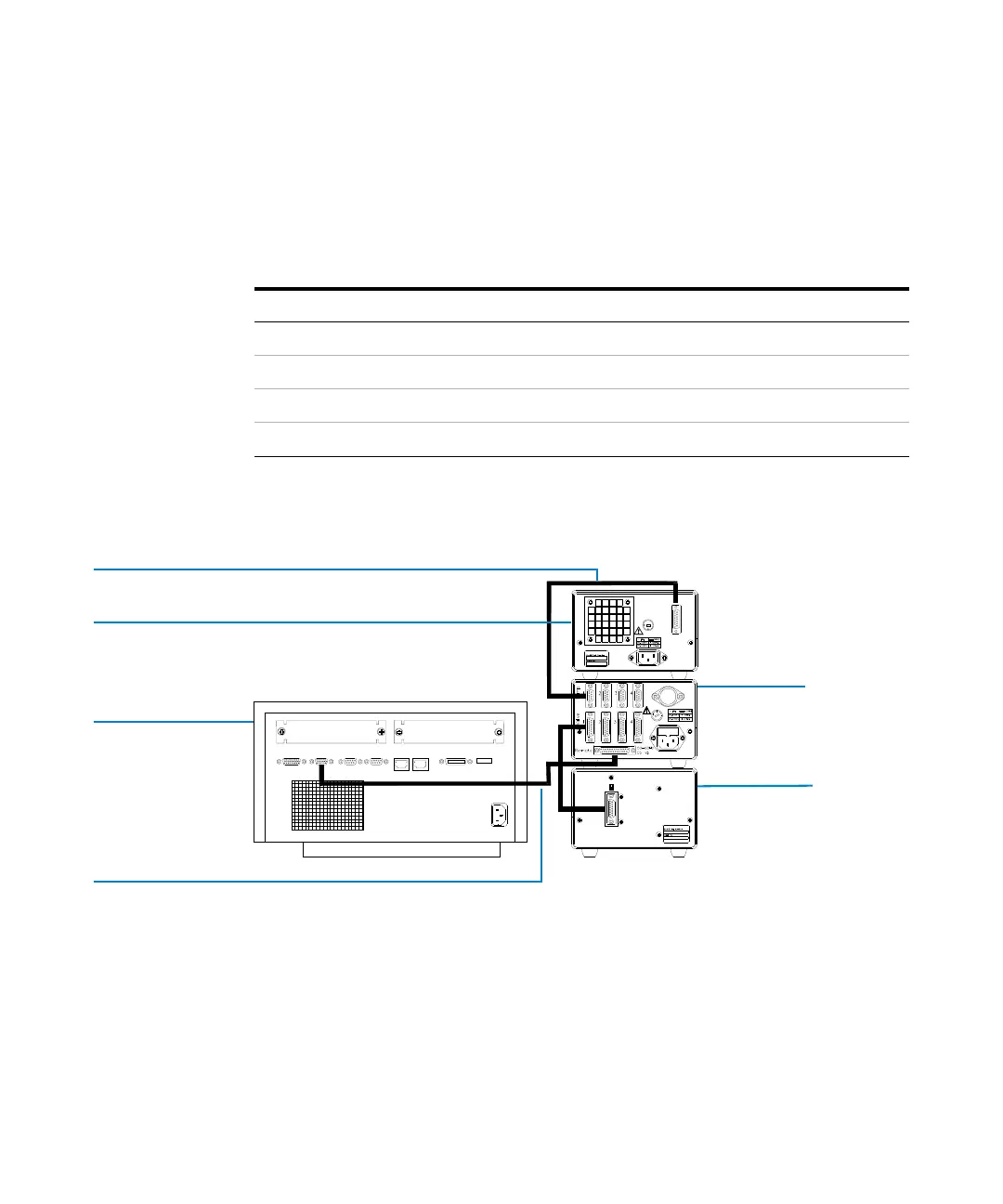
The cables connect to the rear panels of the valve-pump controller, valve unit,
pump and spectrophotometer.
The valve-pump controller can control up to four valve units and pumps. You
connect the valve unit and its pump to channel 1.
Tab le 12 Cables for Valve Unit and Controller
From Controller: To Connector:
Power socket Line-power source
GPIO-to-controller Agilent 8453 spectrophotometer
Controller-to-Valve 1 Valve unit
Controller-to-Pump 1 Peristaltic pump
Figure 14 Connecting Cables
Manual Advance
Remote/Manual
Controle
Remote
50-60 Hz
90 VAmax.
Spectrophotometer
Pump
GPIO-to-controller cable
GPIO-to-controller cable
Controller
Valve unit

 Loading...


