Agilent 8453 Dissolution Testing System Installing and Operating Manual 49
Setting Up 2
Installing a Valve-based Sampling System
Connecting Valve System Tubing
You use the standard cell holder in the Agilent 8453 spectrophotometer with
the valve system. The direction of flow for your samples is from the dissolution
vessels through the valve to the flow cell in the cell holder through the pump
tubing to waste.
The valve tubing kit cell fittings are black and the other fittings are
transparent. You identify the different tubing by the fittings, the colored
heat-shrunk sheaths and the lengths.
To connect valve system tubing:
1 Insert the flow cell into the standard cell holder in the Agilent 8453
spectrophotometer.
2 Connect the dissolution probes to the valve unit, see Figure 7 on page 33
and Chapter 4, “Using the Valve Unit and Valve-pump Controller”. Connect
the 1.5 m pre assembled tubing with colored heat-shrunk sheaths to the
union attached to the dissolution probe. Connect the tubing with colored
heat-shrunk sheaths to the valve inlets.
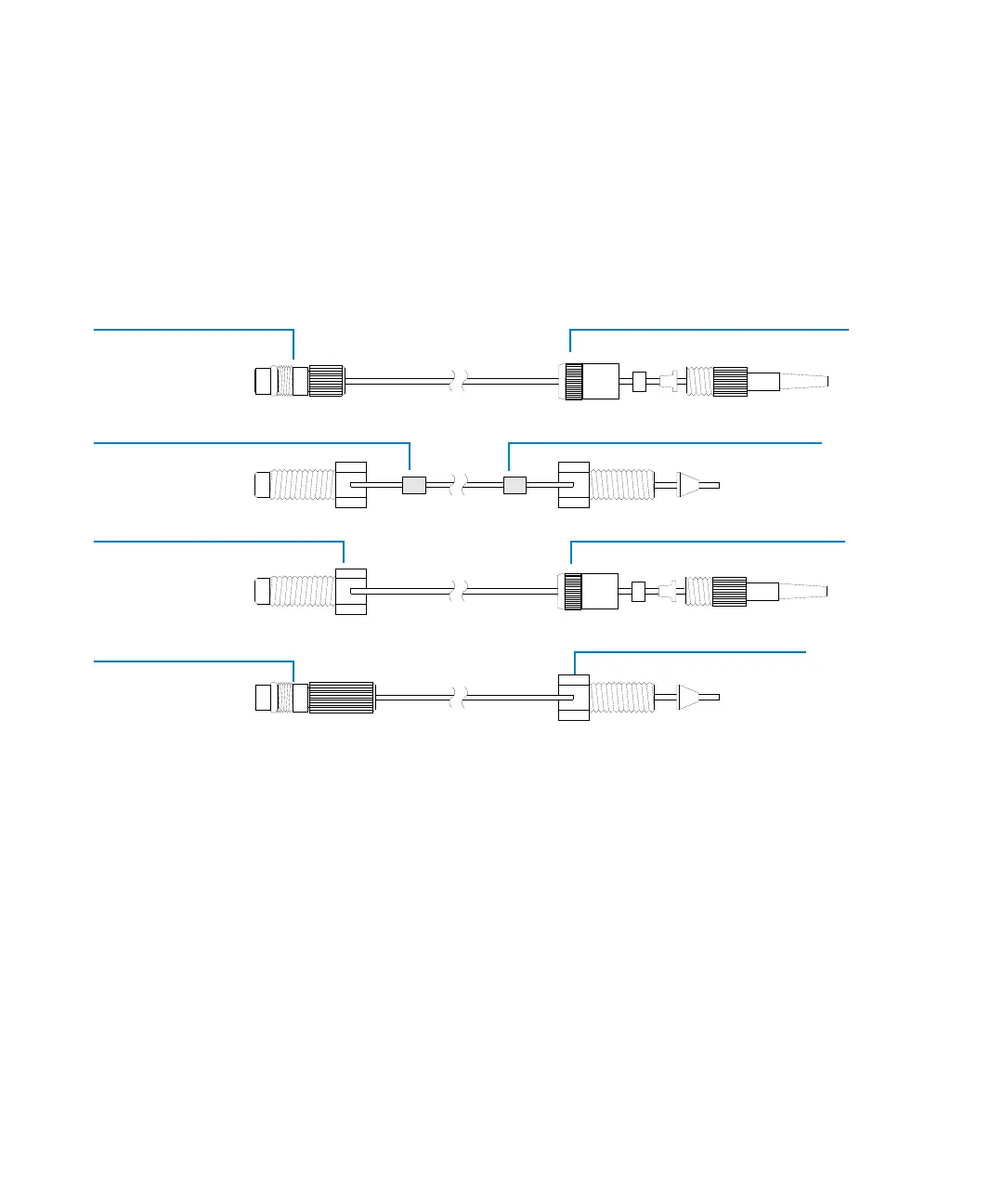
Figure 17 Valve Tubing Kit
Connects flow cell to
pump (0.5 m)
Short cell fitting
Transparent fitting
Connects flow cell to
valve (1.4 m or 2.2 m)
Long cell fitting
Connects waste to
pump (1.5 m)
Transparent fitting
Transparent fitting
Connects dissolution
probe to valve (1.0 m)
Colored sheath
Colored sheath
Valve fitting
Valve fitting

 Loading...


