8-2 Service Guide
Receiver Troubleshooting 8719ET/20ET/22ET
Information on This Chapter 8719ES/20ES/22ES
RF Network Analyzers
Information on This Chapter
Use this procedure only if you have read Chapter 4 , “Start Troubleshooting Here.” Follow
the procedures in the order given, unless instructed otherwise.
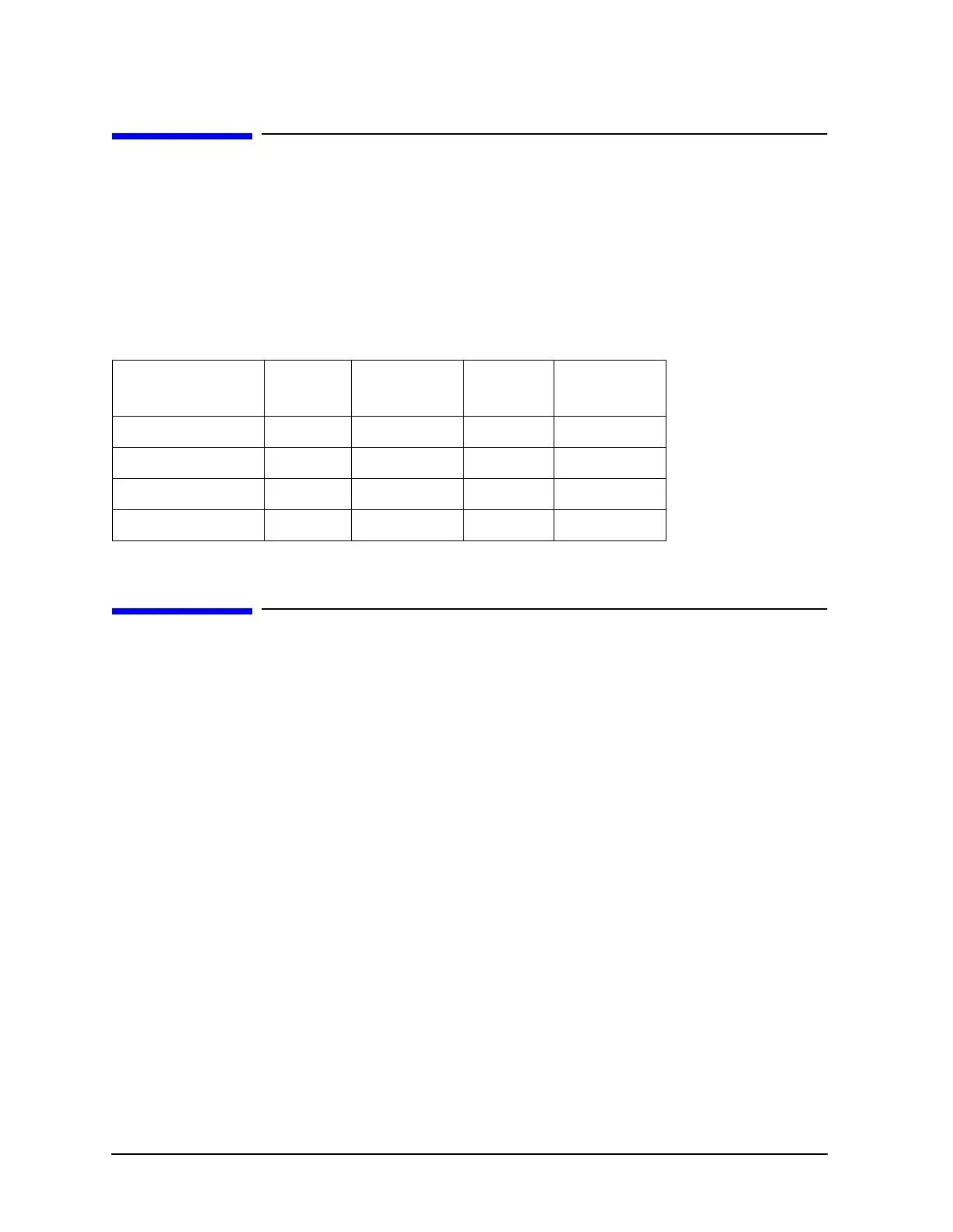
This section can be used to determine which receiver assembly of the instrument is faulty.
The two receiver assemblies that affect all three signal paths are the digital IF (A10) and
reference assemblies (A12). The receiver assemblies that are associated with specific
signal paths are listed in Table 8-1.
Assembly Replacement Sequence
The following steps show the sequence to replace an assembly in the network analyzer.
Step 1. Identify the faulty group. Begin with Chapter 4 , “Start Troubleshooting Here.”
Follow up with the appropriate troubleshooting chapter that identifies the faulty
assembly.
Step 2. Order a replacement assembly. Refer to Chapter 13 , “Replaceable Parts.”
Step 3. Replace the faulty assembly and determine what adjustments are necessary.
Refer to Chapter 14 , “Assembly Replacement and Post-Repair Procedures.”
Step 4. Perform the necessary adjustments. Refer to Chapter 3 , “Adjustments and
Correction Constants.”
Step 5. Perform the necessary performance tests. Refer to Chapter 2 , “System
Verification and Performance Tests.”
Table 8-1 Receiver Assemblies and Associated Paths
Signal Path Port Directional
Coupler
Sampler
Assembly
2nd
Converter
R or R1 internal NA A64 A6
R2 (Option 400) internal NA A67 A6
A1A62A65A4
B2A63A66A5

 Loading...


