6-18
Calibrating for Increased Measurement Accuracy
Frequency Response and Isolation Error Corrections
8. To measure the standard, when the displayed trace has settled, press:
The analyzer displays WAIT - MEASURING CAL STANDARD during the standard measurement. The
analyzer underlines the
softkey after it measures the calibration standard, and computes the
error coefficients.
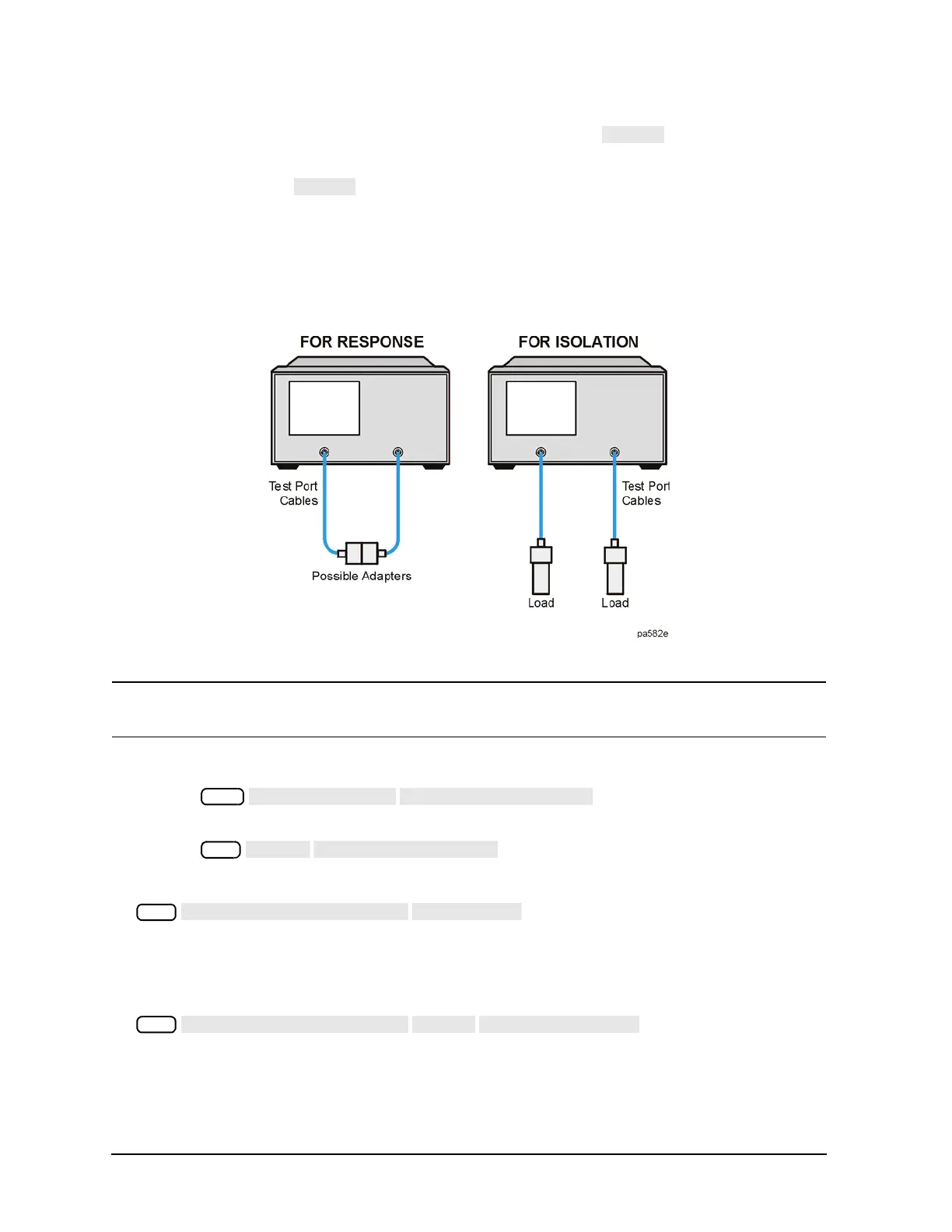
9. Connect impedance-matched loads to PORT 1 and PORT 2, as shown in Figure 6-5. Include the adapters
that you would include for your device measurement.
Figure 6-5 Standard Connections for a Response and Isolation Error Correction for Transmission
Measurements
NOTE If you will be measuring highly reflective devices, such as filters, use the test device,
connected to the reference plane and terminated with a load, for the isolation standard.
10. To help remove crosstalk noise, set the analyzer as follows:
a. Press and enter at least four times more
averages than desired during the device measurement.
b. Press to eliminate one crosstalk path.
11. To measure the calibration standard, press:
12. Return the averaging to the original state of the measurement. For example, reduce the averaging factor
by at least four times or turn averaging off.
13. To compute the isolation error coefficients, press:
The analyzer displays the corrected data trace. The analyzer also shows the notation Cor at the left of
the screen, indicating that the correction is switched on for this channel.

 Loading...


