119
S:\Hp8960\Generic Documents\Manual Operation Getting Started Guide\Pi_manual operation getting started
GPRS Mobile Measurements
In this case, the marker is turned on and positioned at the 600 kHz offset. The
signal level and frequency of the offset where the marker is positioned, are shown
at the top of the display above the graph.
The marker can be turned on by pressing the Graph Control (
F5) key then the
Marker Position (
F2) key. Set the required marker position using the knob or the
numeric entry keys. In addition, the axis values can be changed by pressing the
Axis Control (
F1) key. This allows you to zoom in or out to look at particular
sections of the graph in more detail.
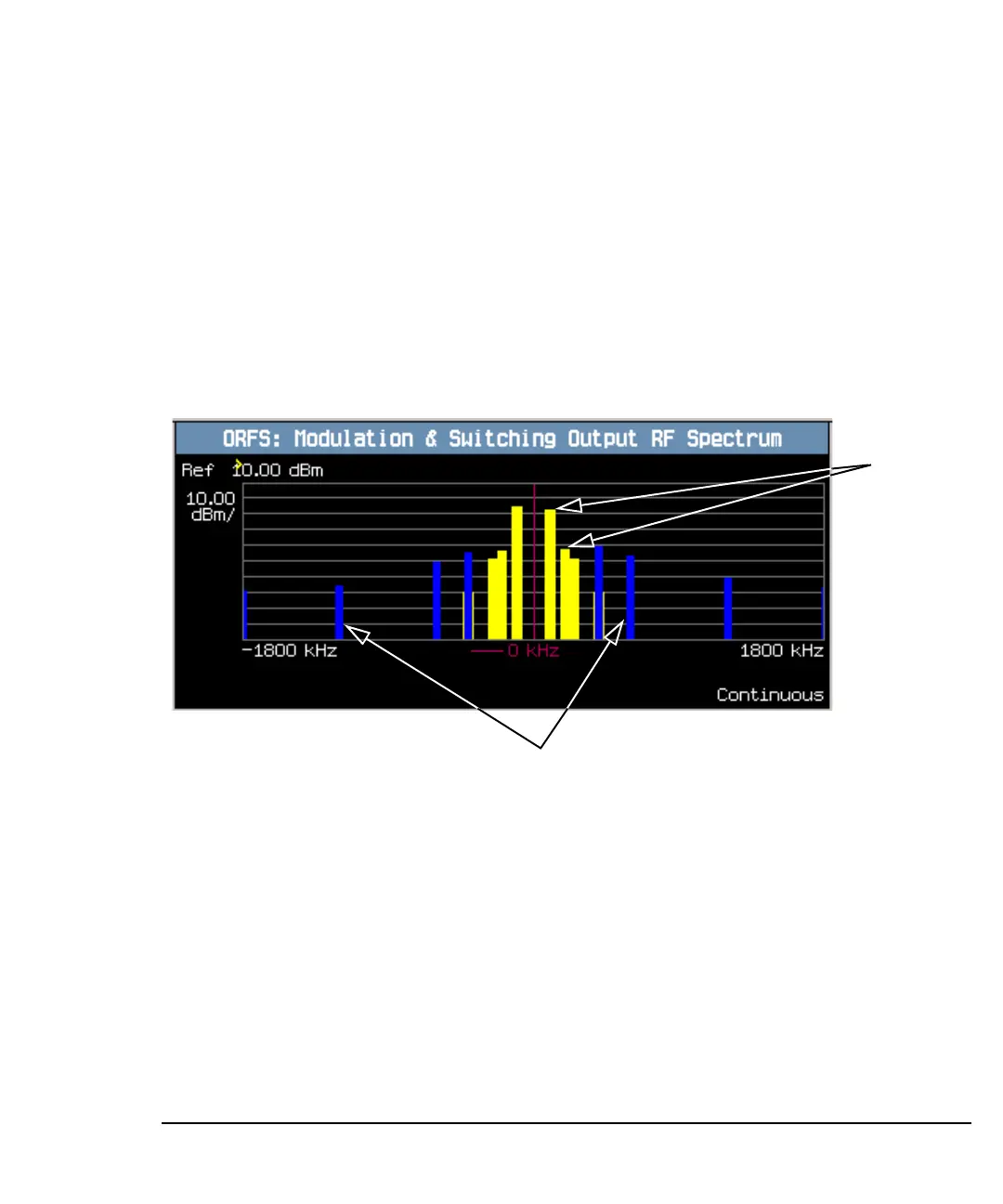
18.Press the Modulation and Switching (
F3) key to access the combined ORFS
bar graph.
A typical combined ORFS due to modulation and switching graph is shown above.
On the display, modulation offsets are shown in yellow, switching offsets are
shown in blue, and the center frequency is indicated by a red vertical line.
If you require details on how to navigate through the Output RF Spectrum graph
menus, see “Output RF Spectrum Graph Menus” on page 120.
Modulation
offsets
Switching offsets
 Loading...


