334 Chapter 11
Assembly Replacement Procedures
RF Section E4440A, E4443A, E4445A
Bottom Switch Removal
1. Drop the front frame. See page 314 for instructions.
2. Refer to Figure 11-17. Remove cables W84, W86, and W87 from the
top switch. Note that two of the cables have identification bands that
correspond to the connector designator 1, or 2, printed on the switch.
3. Remove cable W81 at port 2 of the bottom switch.
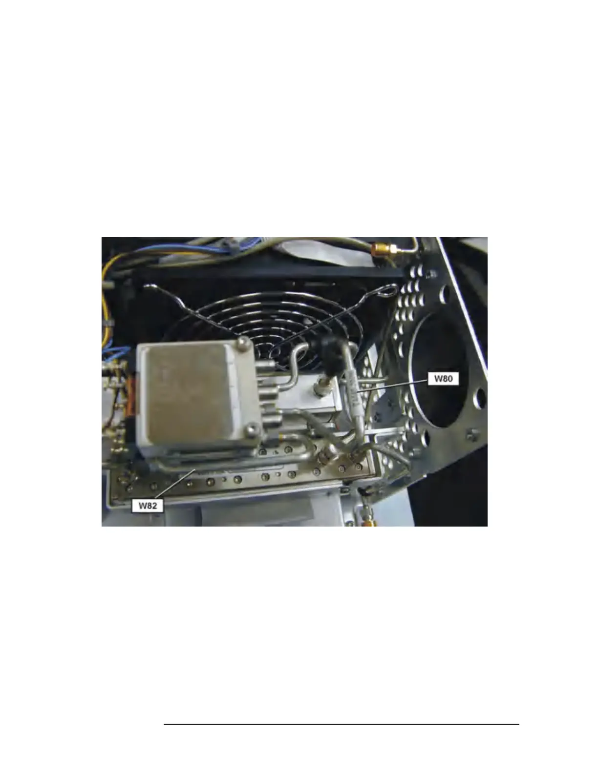
4. Refer to Figure 11-20. Remove W80 from the attenuator and from
port C of the bottom switch and set the cable aside.
Figure 11-20 Bottom Switch Cables
5. Refer to Figure 11-16 and Figure 11-20. Remove cable W82 from the
dual mixer and port 1 of the bottom switch. In order to completely
remove the cable, you will need to position the flat sides of the SMA
connector nut so it will fit between the two switches.
6. Loosen the switch mounting screw located closest to the fan. Loosen
the screw just enough so the threads are clear of the mounting
bracket but do not remove the screw.
7. Loosen the other switch mounting screw just enough to rotate both
switches towards the front of the instrument. This allows room to
unsolder the black jumper wires on the bottom switch.
8. Make note of the black jumper wire position on the bottom switch
 Loading...


