408 Agilent InfiniiVision 3000 X-Series Oscilloscopes User's Guide
27 UART/RS232 Triggering and Serial Decode
6 For both the Rx and Tx signals:
a Connect an oscilloscope channel to the signal in the device under
test.
b Press the Rx or Tx softkey; then, turn the Entry knob to select the
channel for the signal.
c Press the corresponding Threshold softkey; then, turn the Entry knob
to select the signal threshold voltage level.
The threshold voltage level is used in decoding, and it will become
the trigger level when the trigger type is set to the selected serial
decode slot.
The RX and TX labels for the source channels are automatically set.
7 Press the Back/Up key to return to the Serial Decode Menu.
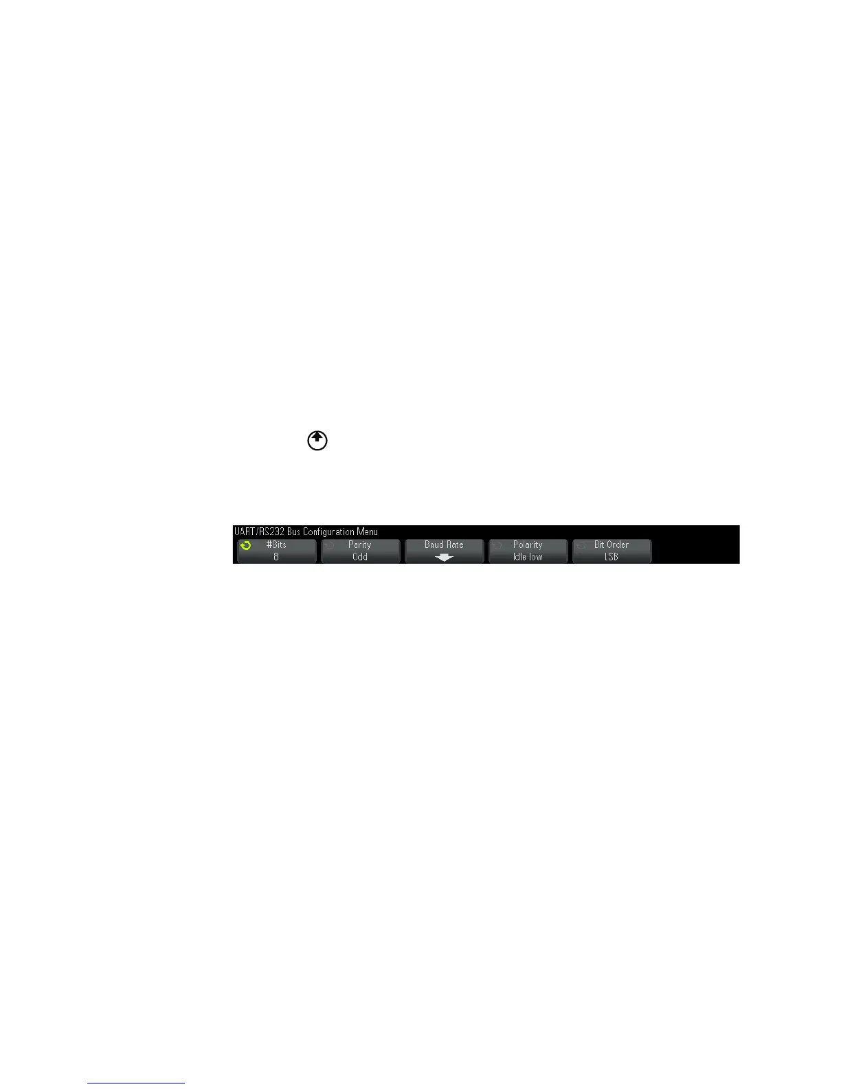
8 Press the Bus Config softkey to open the UART/RS232 Bus Configuration
Menu.
Set the following parameters.
a#Bits — Set the number of bits in the UART/RS232 words to match
your device under test (selectable from 5- 9 bits).
bParity — Choose odd, even, or none, based on your device under test.
cBaud — Press the Baud Rate softkey, then press the Baud softkey and
select a baud rate to match the signal in your device under test. If
the desired baud rate is not listed, select User Defined on the Baud
softkey; then, select the desired baud rate using the User Baud softkey.
You can set the UART baud rate from 1.2 kb/s to 8.0000 Mb/s in
increments of 100 b/s.
dPolarity — Select idle low or idle high to match your device under
test's state when at idle. For RS232 select idle low.
eBit Order — Select whether the most significant bit (MSB) or the least
significant bit (LSB) is presented after the start bit in the signal
from your device under test. For RS232 select LSB.

 Loading...


