127
REPLACEMENT OF MAIN COMPONENTS
3. Check that no refrigerant is left in the main unit, and
perform the following work.
1) Turn the compressor pulley (clutch plate as for No.
2 compressor) a few turns by hand.
2) Loosen each 2 bolts of intake (upper side) and dis-
charge ports.
3) Disconnect the oil tube between the oil tank and
compressor at the oil tank side. (Do not disconnect
the oil tube from the compressor at this time.)
4) Dismount the compressor from the bracket.
NOTE) Take care so that the flanges (o-ring contact
surfaces) of each port are not damaged.
4. Place the removed compressor on the table approx-
imately 4 inch (100 mm) high, and perform the
following work.
1) Disconnect the oil tube from the compressor.
2) Unscrew each 2 bolts of electromagnetic compres-
sor capacity valve and intake ports.
3) Unscrew 2 bolts to remove the electromagnetic
compressor capacity valve with the stay.
4) Remove the compressor heater from the compres-
sor.
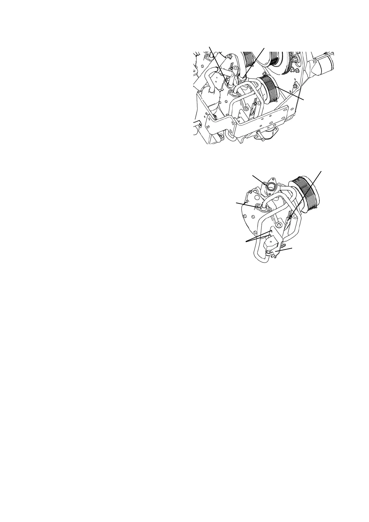
Pulley
Discharge port
Intake port
Compressor heater
Bolts
Stay
Intake port
Electromagnetic
compressor
capacity port
 Loading...