128
REPLACEMENT OF MAIN COMPONENTS
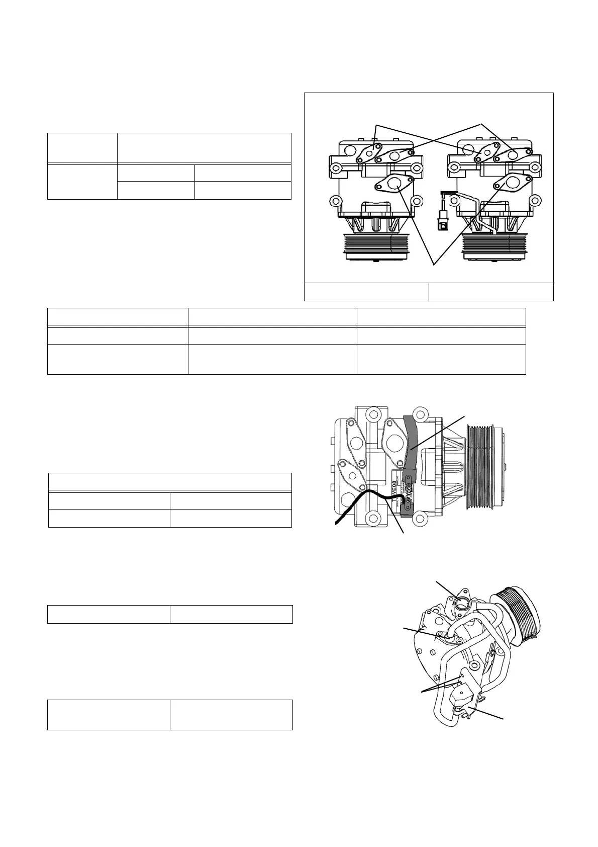
[Reassembling]
1. Remove the port cover of the new compressor.
Supply the specified amount of refrigeration oil
through the intake and discharge ports.
NOTE) If the refrigerant oil adheres on the surface of
the compressor main unit, wipe out all the oil.
2. Mount the new o-rings to the intake and electromag-
netic compressor capacity valve ports grooves.
NOTE) Apply refrigeration oil to the o-ring, and install
it so that it is not damaged.
3. Mount the compressor heater on the compressor.
NOTE) Mount the compressor heater paying attention
to the direction and position of the heater and
heater wire harness referring to the right fig-
ure.
4. Mount the electromagnetic compressor capacity
valve on the compressor.
1) Mount the stay and tighten 2 bolts.
2) Tighten each bolts of electromagnetic compressor
capacity valve and intake (lower side) ports.
NOTE) When mounting each port, pay attention so
that the o-rings will not be caught.
5. Connect the oil tube to the compressor.
NOTE) Insert the oil tube until it hits a dead end.
No. 1 (Without clutch) No. 2 (With clutch)
Intake ports
Discharge ports
Electromagnetic compressor
capacity valve ports
Refrigeration
oil name
Specified amount to be supplied
NL10
Intake side 1.7 ft oz. (50 cm
3
)
Discharge side 5 ft oz. (150 cm
3
)
Port Inner diameter Wire diameter
Intake side Ф1-1/8 inch (Ф29.8 mm) Ф3/32 inch (Ф2.3 mm)
Electromagnetic compressor
capacity valve side
Ф5/8 inch (Ф17.4 mm) Ф3/32 inch (Ф2.3 mm)
Compressor heater
Heater wire harness
Compressor heater mounting direction
Wire harness Port side
Spring Pulley side
Stay
Bolts
Intake port
Electromagnetic
compressor capacity
port
Tightening torque 6.3 lb·ft (8.5 N·m)
Tightening torque
8.9 ~ 13.3 lb·ft
(12 ~ 18 N·m)
 Loading...