Publication 1394-5.0 — May 2000
B-28 Interconnect and CE Diagrams
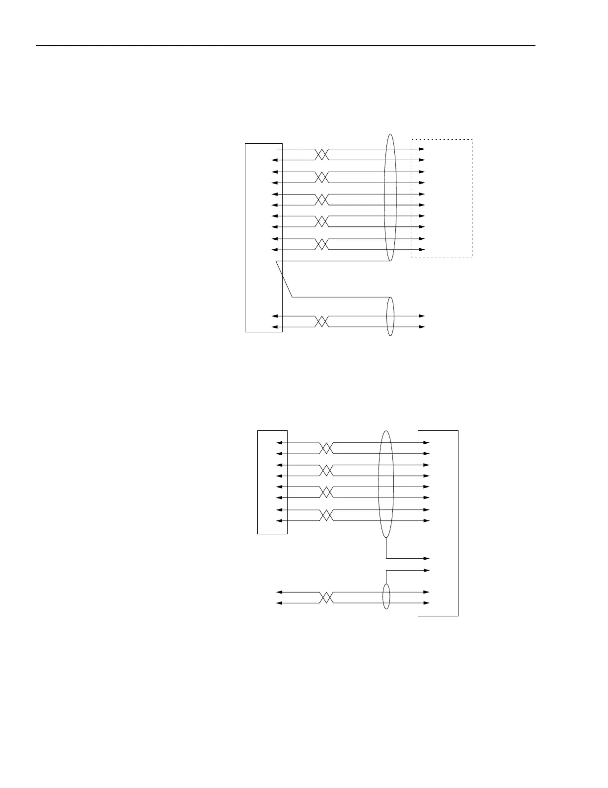
Figure B.22
1394-GE15 Cable Connections
1
Customer supplied 5V DC power source is required for encoder board whether encoder supply voltage is
5V or not.
Figure B.23
1394-GR04 Cable Connections
7
1
2
3
4
5
6
8
9
12
10
11
Black
Yellow
White
Black
Green
Black
Blue
Black
Red
Black
Shield
NC
Strobe
A High
A Low
B High
B Low
Z High
Z Low
+5V Out
Common Out
1394 Encoder
Feedback Connector
Flying Leads to
Incremental Encoder or
Customer-Supplied Termination
NC
Shield
Red
Black
+5V Input
Common In
Encoder Power
(ENC. PWR)
Cable is Belden 9505
Cable is Belden 9501
1
4100-REC Axis 0 or
Axis 1 Connector
9
2
4
10
5
11
6
12
9
7
1
2
3
4
5
6
12
12
10
11
Encoder Power
(ENC. PWR)
+5V DC Com
+5V DC
1394 GMC or GMC Turbo
Encoder Feedback Connector
Cable is Belden 9504
Cable is Belden 9501
Black
Red
White
Black
Green
Black
Blue
Black
Red
Black

 Loading...