Rockwell Automation Publication 290E-UM001B-EN-P - June 2012 41
Installation and Wiring Chapter 2
Dimensions
Dimensions are shown in millimeters (inches). Dimensions are not intended
to be used for manufacturing purposes. All dimensions are subject to change.
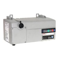
Figure 16 - Dimensions for Bulletin 290E/291E
Front View
Right Side View
Conduit Gland Entrance
ArmorConnect Internal Power
Supply Gland Plate (optional)
ArmorConnect Media
Gland Entrance (optional)
ArmorConnect Source Brake
Gland Plate (optional)
1 in. conduit opening
0.75 in. conduit opening
Line
Control
Motor
Line
Motor
Control
Line
Motor
Source Brake
152,65
(6.0)
48,5
(1.9)
24,25
(1.0)
38,49
(1.5)
57,13
(2.3)
37
(1.5)
260
(10.2)
130
(5.1)
166,5
(6.6)
202,05
(8.0)
65
(2.6)
170
(6.7)
217,83
(8.6)
37
(1.5)
57,13
(2.3)
24,25
(1.0)
38.49
(1.5)
48,5
(1.9)
37
(1.5)
57,13
(2.3)
38,61
(1.5)
24,25
(1.0)
37
(1.5)
57,13
(2.3)
38,49
(1.5)
48,5
(1.9)
For proper heat dissipation and product operation, mount the ArmorStart LT in the
vertical orientation as shown.

 Loading...


