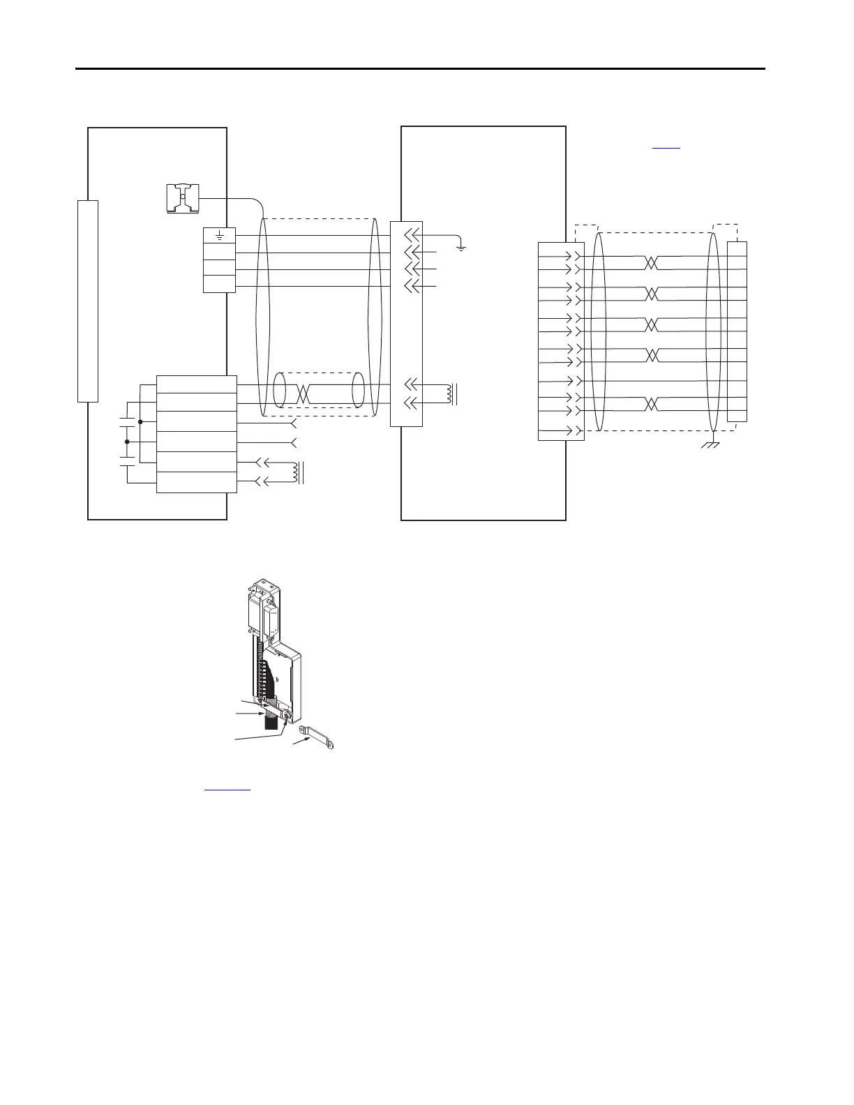
EasyManuals Logo

Allen-Bradley Kinetix 6000 User Manual

Allen-Bradley Kinetix 6000
290 pages
To Next Page IconTo Next Page
To Previous Page IconTo Previous Page
Page #204 background imageLoading...
Page #204 background image
204 Rockwell Automation Publication 2094-UM001J-EN-P - March 2017
Appendix A Interconnect Diagrams
Figure 101 - AM Module (230V) Wiring Example with TL-Series™ Motors (Bulletin TLY-A)
5
3
2
1
BR+
BR-
7
9
W
V
U
GND
1
2
3
4
5
6
7
8
9
10
11
12
13
14
15
4
3
2
1
6
5
4
3
2
1
Green/Yellow
Blue
Black
Brown
Black
White
W
V
U
MBRK -
MBRK +
COM
PWR
DBRK -
DBRK +
BR+
BR-
AM+
AM-
BM+
BM-
IM+
IM-
+5VDC
ECOM
WHITE/BLUE
GREEN
WHITE/GREEN
GRAY
WHITE/GRAY
BLACK
WHITE/BLACK
RED
WHITE/RED
1
2
3
4
5
10
14
6
12
S1
S2
S3
YELLOW
WHITE/YELLOW
13
8
SHIELD
22
23
15
24
17
19
9
10
11
12
13
14
Motor Brake
Three-phase
Motor Power
Motor Feedback
TLY-Axxxx-H (230V)
Servo Motors with
Incremental Feedback
2090-CFBM6DF-CBAAxx (flying-lead) or
2090-CFBM6DD-CCAAxx (with drive-end connector)
Feedback Cable
Notes 16, 17
Resistive Brake
Connections
Motor/Resistive
Brake (BC) Connector
Motor Power
(MP) Connector
Cable Shield
Clamp
Note 10
IAM (inverter) or AM
Module
Note 15
2090-CPBM6DF-16AAxx
Motor Power and Brake Cable
Notes 16, 18
Use 2090-CPWM6DF-16AAxx
cable for non-brake
applications.
User Supplied
24V DC
Refer to low-profile connector
illustration (lower left)
for proper grounding technique.
Grounding Technique for
Feedback Cable Shield
Turn clamp over to hold
small cables secure.
Exposed shield secured
under clamp.
Clamp Screws (2)
Clamp
Refer to table on page 188
for note information.
Motor Feedback
(MF) Connector
2090-K6CK-D15M
Connector Kit
2090-K6CK-D15M
Low-profile Connector Kit
Refer to Low Profile Connector Kit Installation Instructions,
publication 2094-IN007
, for connector kit specifications.

Table of Contents

Other manuals for Allen-Bradley Kinetix 6000

Questions and Answers:

Question and Answer IconNeed help?

Do you have a question about the Allen-Bradley Kinetix 6000 and is the answer not in the manual?

Allen-Bradley Kinetix 6000 Specifications

General IconGeneral
Control TypeDigital
FeedbackResolver, Encoder
Protection RatingIP20
Power Range0.4…22 kW
CommunicationEthernet/IP
Ambient Temperature0°C to 50°C
AxisSingle-axis, Multi-axis
SafetySafe Torque-Off
Control ModesVelocity, Torque, Position
Relative Humidity5% to 95% (non-condensing)
Vibration Resistance5.9 m/s² (0.6 g) from 10 Hz to 500 Hz
Shock Resistance15 g, 11 ms
Storage Temperature-40°C to 70°C

Related product manuals