Publication 1734-UM011A-EN-P - February 2004
2-2 Install the 1734-AENT Adapter
Identify Module
Components
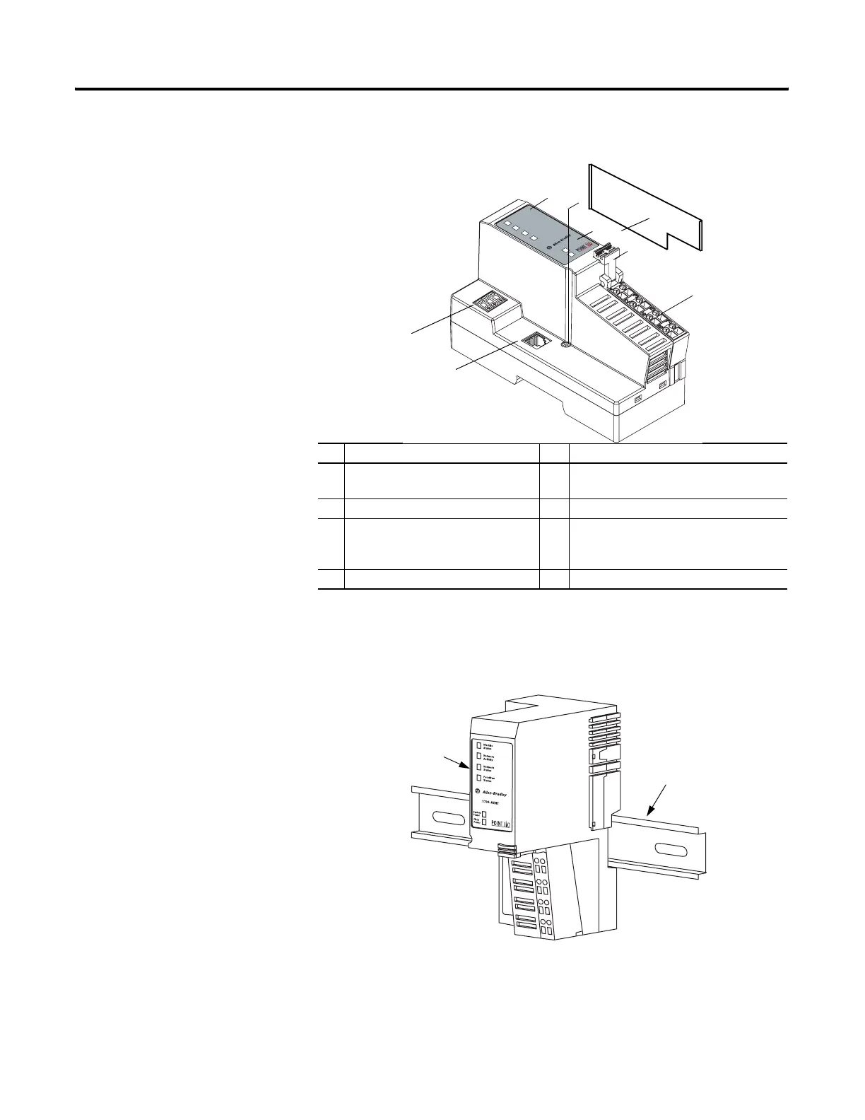
Use the following illustration to identify the external features of the POINT
I/O EtherNet/IP adapter.
Mount the Adapter on a DIN
Rail Before
Installing Modules
Use the following procedure to mount the adapter on a new system before any
I/O modules have been installed.
1. Position the adapter (A) vertically above the DIN rail (B).
2. Press down firmly to install the adapter on the DIN rail. The locking
mechanism will lock the adapter to the DIN rail.
Description Description
1 Ethernet Network RJ45 Connector 5 System Power and Field Power
Indicators
2 Network Address Thumbwheel 6 Removable Terminal Block (RTB) Handle
3 Indicators - Module Status,
Network Activity, Network Status,
and PointBus Status
7 Removable Terminal Block (RTB)
4 DIN Rail Locking Screw (orange) 8 Safety Endcap
Module
Status
Network
Activity
Network
Status
PointBus
Status
1734-AENT
Field
Power
System
Power
1
6
5
4
3
8
02
0
43247aent1
A
B
43520
 Loading...