Publication 1734-UM011A-EN-P - February 2004
4-2 Configure the 1734-AENT for Direct Connection in RSLogix 5000
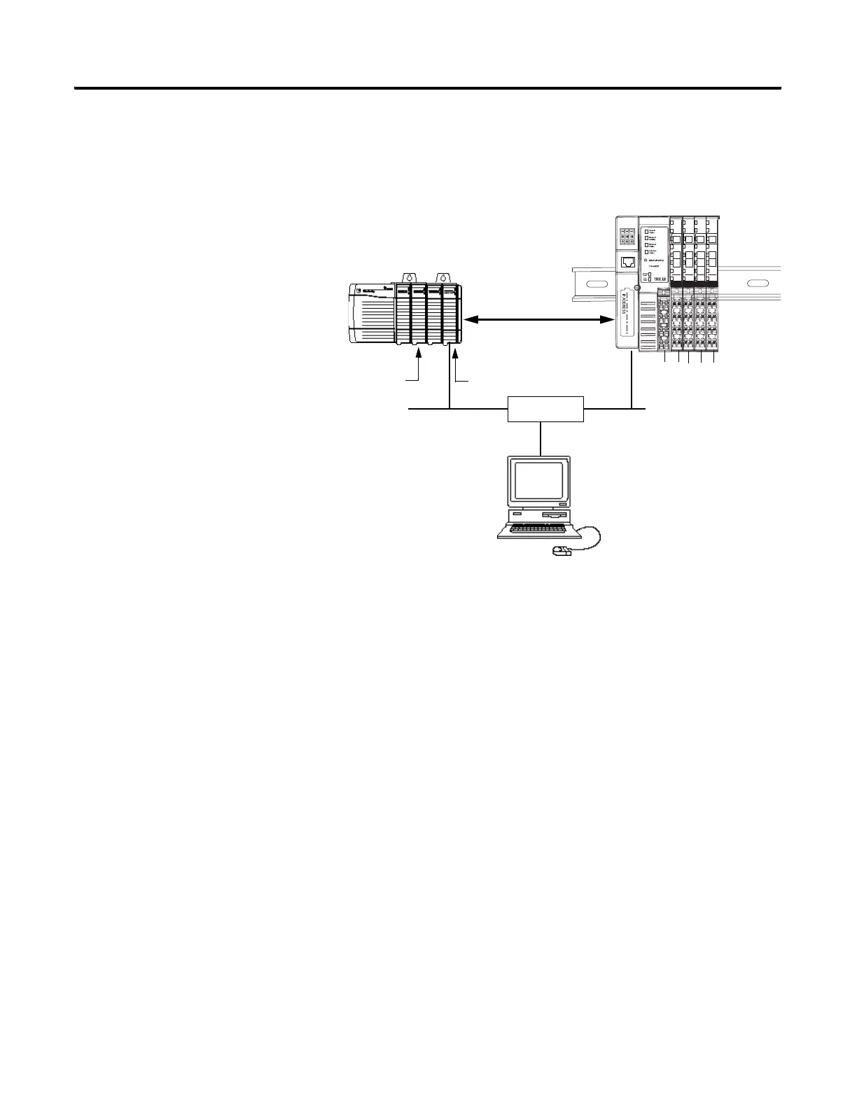
Set Up the Hardware
In this example, a ControlLogix chassis contains the Logix 5555 processor in
slot 1 and a 1756-ENBT bridge module in slot 3. The 1734-AENT adapter is
mounted on a DIN rail in slot 0, with a 1734-OW2/C relay output module in
slot 1, a 1734-OV4E/C sink output module in slot 2, and a power supply (not
shown).
To work along with this example set up your system as shown above.
• Note that in the example application, the Logix5555 controller and
1756-ENBT module (firmware version 2.3 or higher) are assumed to be
in the slots shown above.
• Verify the IP addresses for your programming terminal, 1756-ENBT
module, and 1734-AENT adapter.
• Verify the position (slot) of the I/O modules on the DIN rail.
• Verify that all wiring and cabling is properly connected.
• Make sure your communication driver (e.g., AB_ETH-1 or
AB-ETHIP-1) is configured in RSLinx as described in Appendix B.
Local
Chassis
POINT I/O
Logix5555
Controller (slot 1)
1756-ENBT
10.88.70.4 (slot 3)
Data
Switch
10.88.70.26
Programming
Terminal
Slot 0 1 2 3
1734-AENT
10.88.70.2
Slot 0 1 2 3 4
31393-M
 Loading...