Publication 1734-UM011A-EN-P - February 2004
4-8 Configure the 1734-AENT for Direct Connection in RSLogix 5000
Because None was entered as the Comm Format on the Module
Properties window, the RPI (requested packet interval) is disabled.
5. Click on the Finish button to accept the configuration.
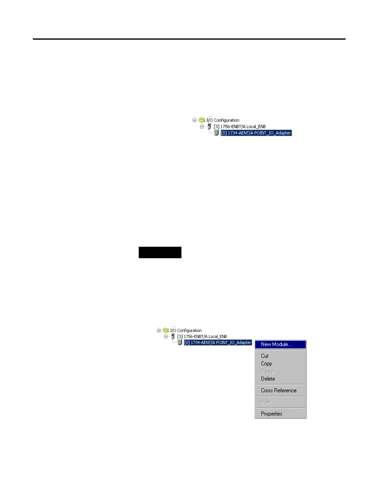
The 1734-AENT adapter will appear indented under the local 1734-ENBT
in the I/O Configuration folder.
Add the POINT I/O Modules to the I/O Configuration
You must now add the POINT I/O modules to the I/O Configuration List
under the 1734-AENT adapter.
In this example, you will add a 1734-OW2 relay output and a 1734-OV4E sink
output module with standard configurations. Use these steps as a guide when
you are configuring different I/O modules for your system.
Add the Relay Output Module
1. Right click on the remote 1734-AENT adapter under the I/O
Configuration folder and select New Module.
TIP
This example application uses the I/O modules’ default
configurations. For more information, see the POINT I/O
Selection Guide, publication no. 1734-SG001.
 Loading...