UB25 LINEAR DC RESISTANCE WELDING CONTROL
990-665 B-1
APPENDIX B
ELECTRICAL AND DATA CONNECTORS
Introduction
This Appendix describes the electrical and data connectors located on the rear panel of the DC25. Each
connector is illustrated with pin identification. Following each picture is a table listing the technical
specifications for that connector. Connectors are described in the order in which they appear on the rear
panel of the DC25, starting at the top left.
Note: The specifications listed in this Appendix may be changed without notice.
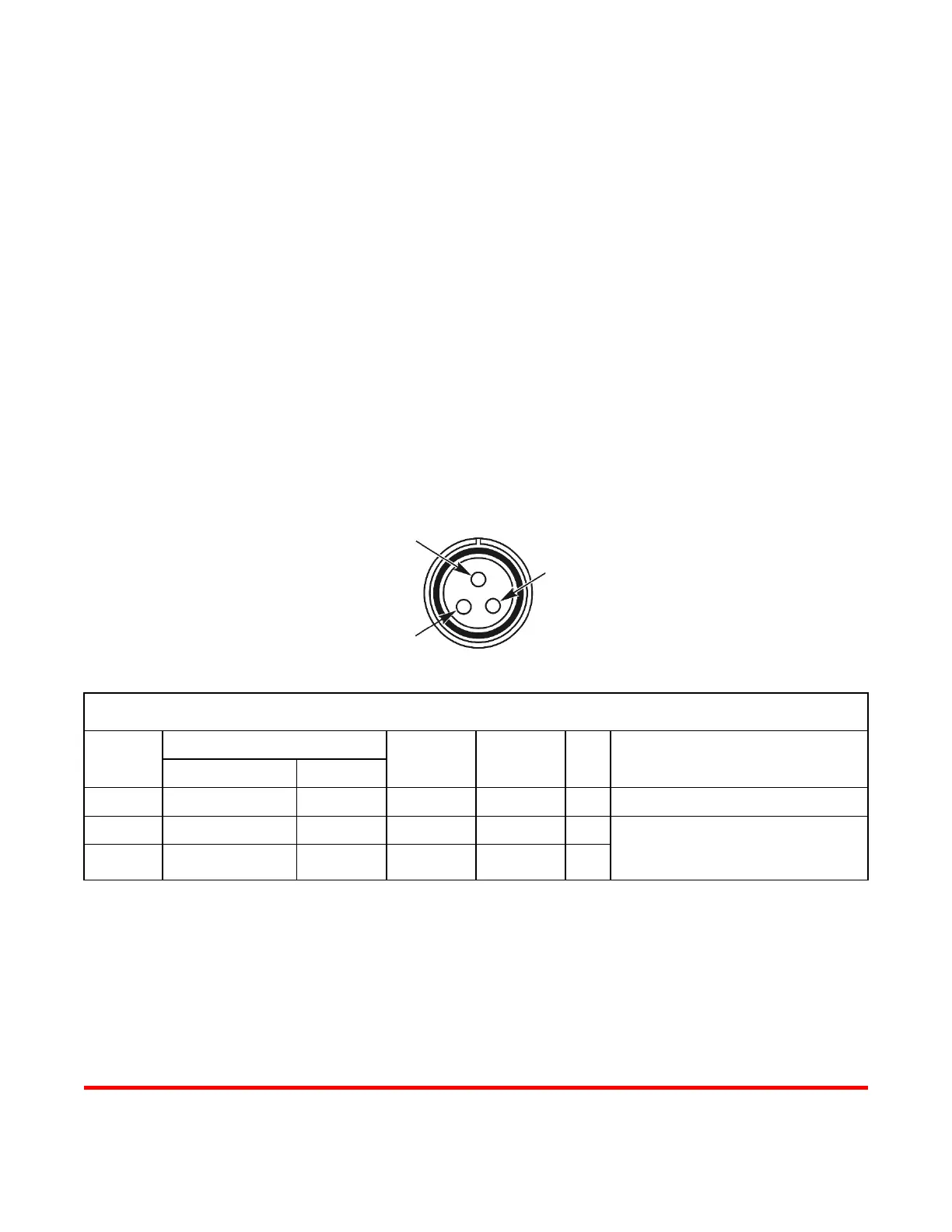
Voltage Sense Input
VOLTAGE SENSE INPUT CONNECTOR SPECIFICATIONS
PIN NO.
SIGNAL
MAX
VOLTAGE
MAX
CURRENT
I/O COMMENTS
NAME TYPE
1 AGND Analog Ground
2 Input #1 Pulse 15 V 0.1 A I Signal is differential between Input #1
and Input #2
(polarity is not important).
3 Input #2 Pulse 15 V 0.1 A I