CHAPTER 5: SETUP SOFTWARE
UB25 LINEAR DC RESISTANCE WELDING CONTROL
990-665 5-19
Section VI. Relay Settings
Function
The Power Supplies four relays can be programmed to activate outputs under eight user-programmed
conditions. Relay connections are made through the 25-pin connector I/O Signal Interface A on the rear
of the Power Supply. See Appendix B, Electrical and Data Connectors for pin connections. Appendix F,
Relay Timing Diagrams provides the timing sequences for the four relays.
Programming Instructions
NOTE: Programming for each of the relays is identical.
1 From the MAIN MENU, press the 6 key
to get the relay menu.
2 From the RELAY menu, press the 1, 2,
3, or 4 key to select a relay menu.
3 Press the 1 key to toggle the relay
contact signal state: ON (closed) or OFF
(open).
4 Press the 2 key to select the WHEN
menu. This menu allows you to choose
when the relay is activated. The WHEN
states are described on the next page.
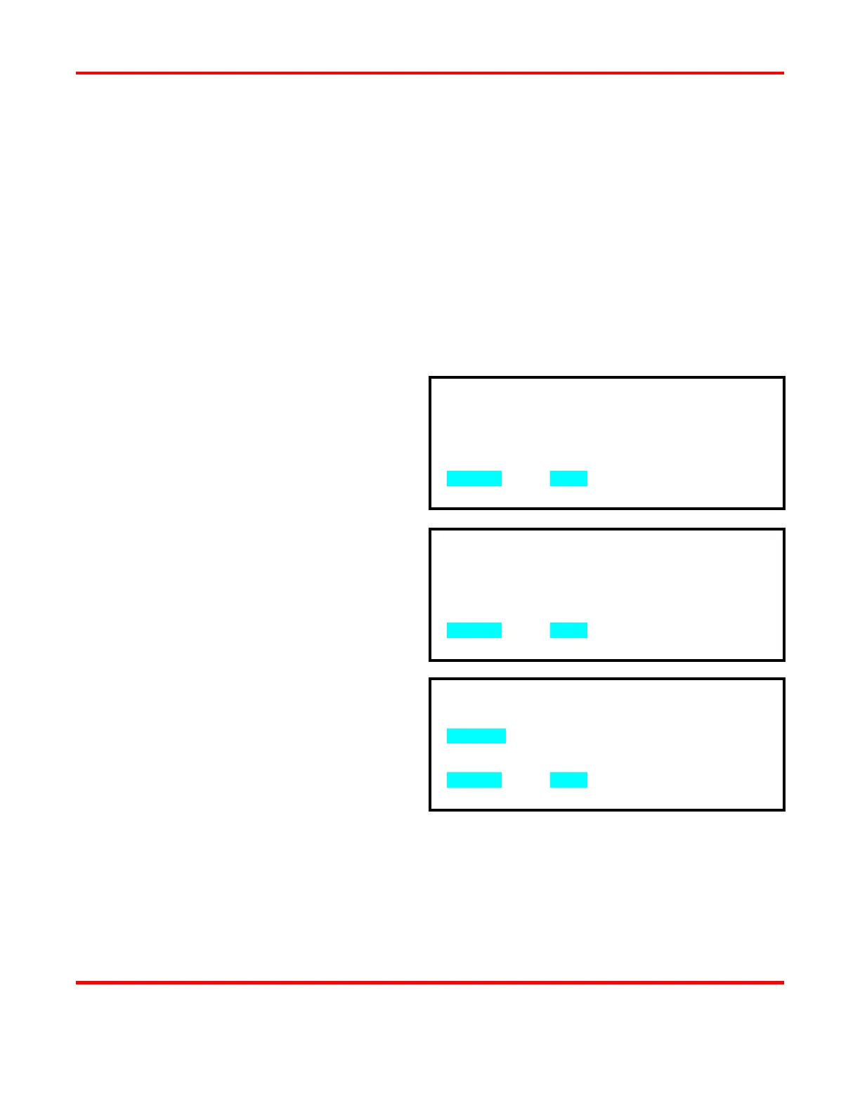
5 Use the numeric keypad to select when
the relay will energize. The display
screen automatically returns to the
1. SET RELAY TO : ON
2. WHEN : ALARM
NUMBER Select, MENU Previous menu
1. RELAY 1 : ON WHEN ALARM
2. RELAY 2 : ON WHEN ALARM
3. RELAY 3 : ON WHEN ALARM
4. RELAY 4 : ON WHEN ALARM
NUMBER Select, MENU Previous menu
1. WELD 6. P1 LOW LIMIT
2. END OF WELD 7. P2 HIGH LIMIT
3. ALARM 8. P2 LOW LIMIT
4. OUT OF LIMITS
5. P1 HIGH LIMIT
NUMBER Select, MENU Previous menu