CHAPTER 2: GETTING STARTED
UB25 LINEAR DC RESISTANCE WELDING CONTROL
990-665 2-3
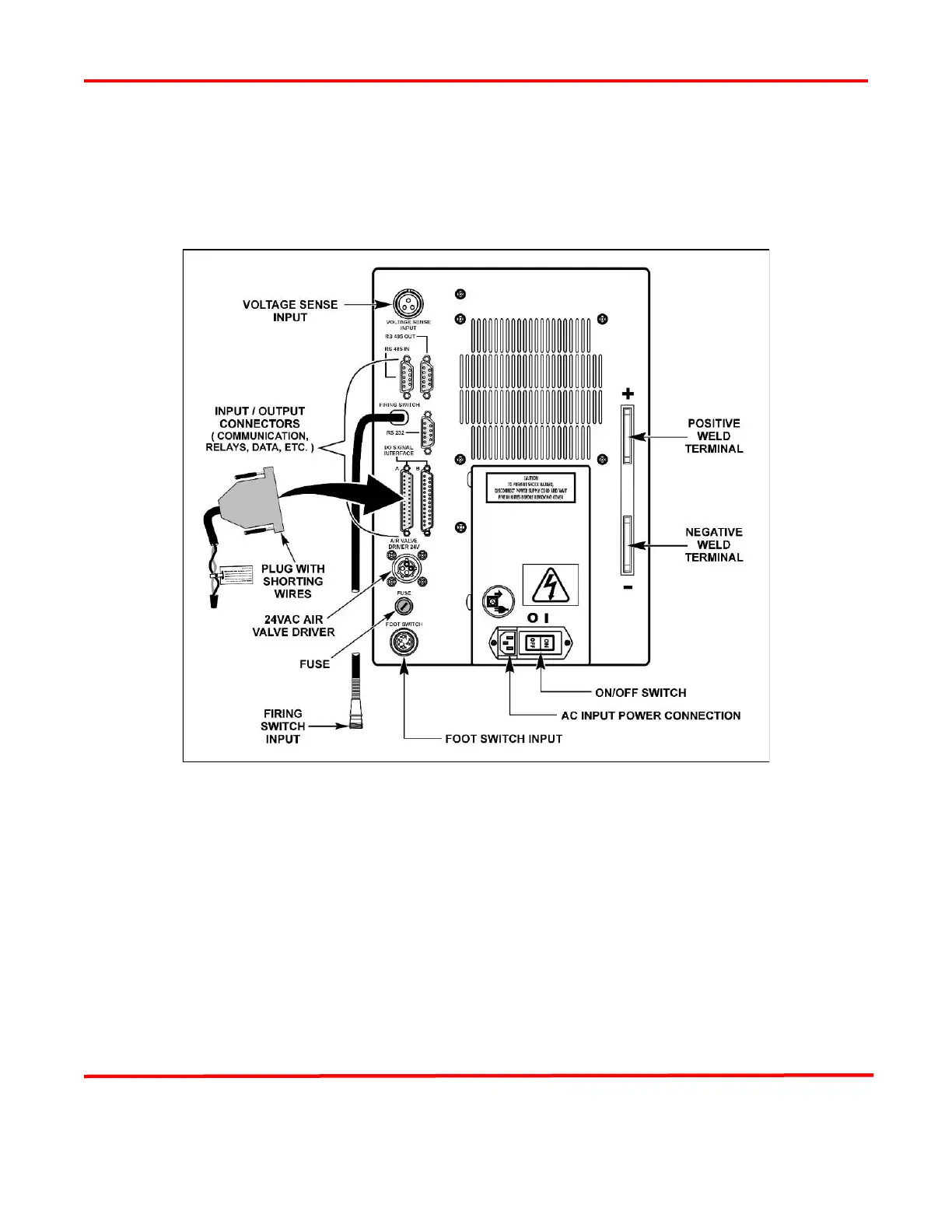
Section III: Electrical and Data Connections
All connections between the Power Supply, switches, the weld head, and external equipment, such as PLC
and data, are made on the rear panel.
UB25 Rear Panel Connections
NOTE: The Power Supply is shipped with two 25-pin mating plugs installed on the two I/O connectors
on the rear panel (the plug for Connector B is not shown for clarity). The Power Supply will not function
if these plugs are not installed. The plug connected to I/O Connector A is pre-wired with a two-wire lead
for the Emergency Stop Switch. For details, see Chapter 1, Section V, Emergency Stop Switch And 24V
Jumpers.
NOTE: Wiring of cables and connectors going to the Power Supply should only be done by qualified
service personnel. Connector pin identification and specifications for the rear panel connectors are located
in Appendix B. Electrical and Data Connectors.
NOTE: For clarity, illustrations in the rest of this manual do not show the power cable connected to the
Power Supply, even though the power cable must be connected in order to operate the Power Supply.