UB25 LINEAR DC RESISTANCE WELDING CONTROL
990-665 F-1
APPENDIX F
RELAY TIMING DIAGRAMS
Introduction
Instructions for relay setup are in Chapter 5, Section VI, Relay Settings. Instructions cover the ON/OFF
state, the SET RELAY TO and the WHEN states:
• WELD
• END OF WELD
• ALARM
• OUT OF LIMITS
− P1 HIGH LIMIT
− P1 LOW LIMIT
− P2 HIGH LIMIT
− P2 LOW LIMIT
The following diagrams show the timing sequence for each relay WHEN state.
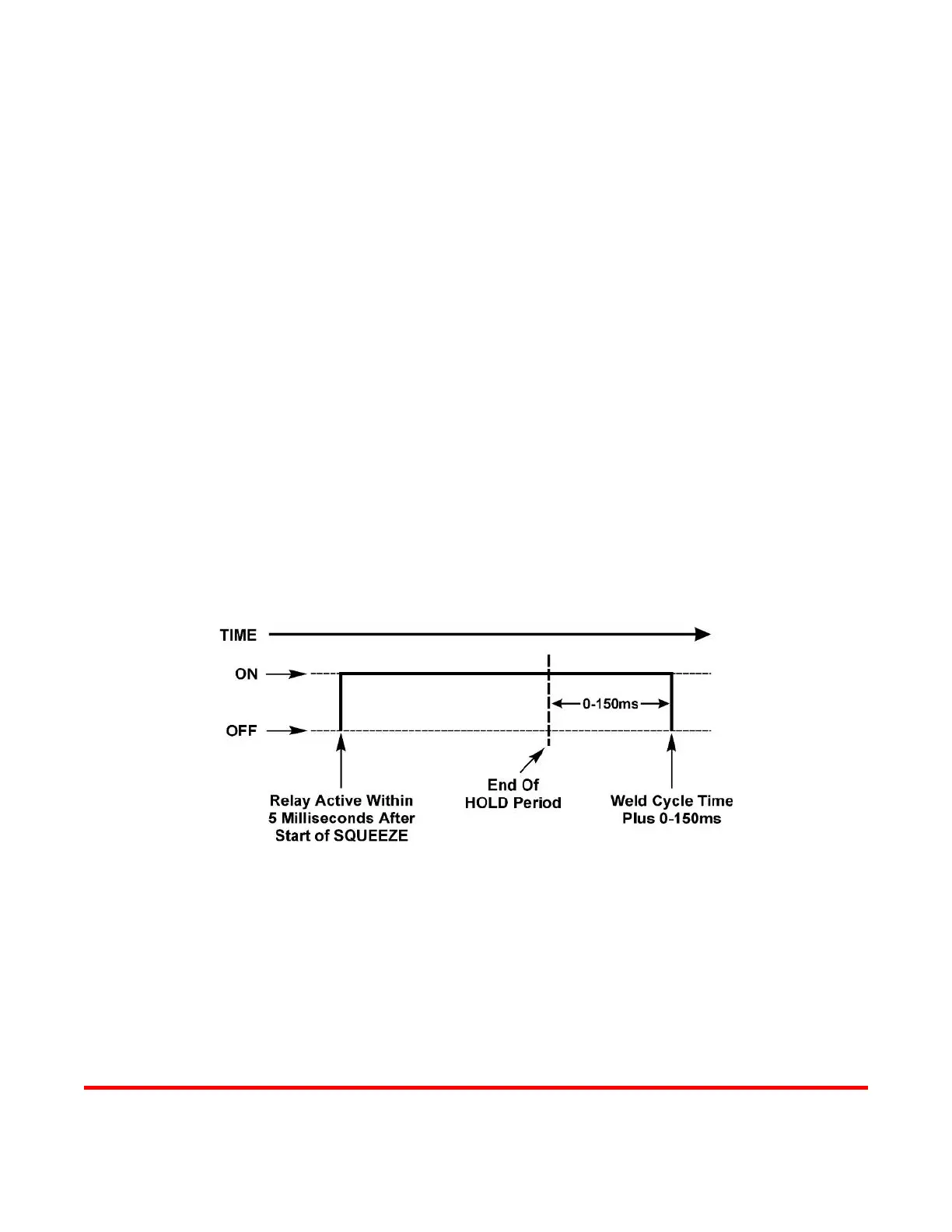
WELD
When welding, the relay output signal will start within 5 milliseconds after the start of SQUEEZE and
will stay energized for 0-150 milliseconds after the end of the HOLD period.