CHAPTER 3: USING UB25 WELDING FUNCTIONS
UB25 LINEAR DC RESISTANCE WELDING CONTROL
3-2 990-665
Section II. Weld Schedules
Definition
Weld Schedule is the name given to each of 99 separate weld profiles stored in the Power Supply,
numbered from 01 → 99. A weld profile is the graphic representation [or waveform] of the numeric weld-
time and weld-energy values. NOTE: There is an additional weld schedule numbered 00, which can be
used as a "scratch pad" to develop new weld schedules.
When time and energy values are entered using the numeric keypad, the Power Supply displays a line-
graph of the weld profile on the LCD screen. You can see the graph change as you enter new time and
energy values.
Weld profiles may be programmed for single-pulse, upslope / downslope, or dual-pulse operation. Weld
schedules may also use special monitoring features of the Power Supply such as Energy Limit, Active
Part Conditioner, and Pre-Weld Check. These features are described later in this chapter.
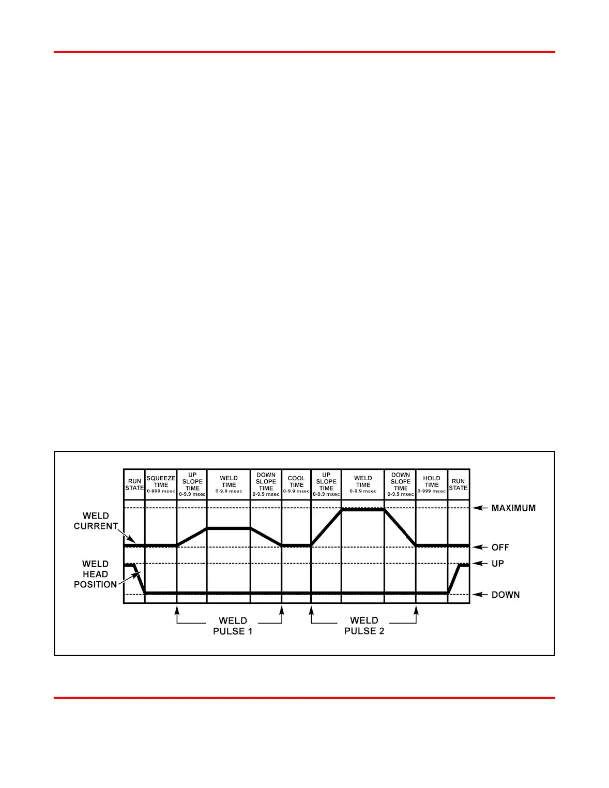
Weld Sequence Timing
A weld schedule is a unique heat profile programmed in constant current, voltage, or power that is
applied over a fixed time period, to resistance weld different parts. The entire weld can include all of the
following time periods: Squeeze Time, Upslope 1, Weld Pulse 1, Downslope 1, Cool Time, Upslope 2,
Weld Pulse 2, Downslope 2, and Hold Time. The sample dual-pulse profile [or waveform] below shows
the weld current and the corresponding position of the weld head. The graph labeled
WELD CURRENT is
what displays on the LCD when you schedule a weld profile.
Sample Weld Sequence (Dual-Pulse)