CHAPTER 5: SETUP SOFTWARE
UB25 LINEAR DC RESISTANCE WELDING CONTROL
5-10 990-665
weld schedule to allow the weld head to close and the weld force to stabilize before the weld
current starts.
NOTE: In addition to the debounce time, there is a delay of no greater than 2.5 ms before
the start signal is recognized by the Power Supply.
• REMOTE can be used in automated applications or when using a PLC to control the weld
head. The weld energy sequence is initiated via the Remote Schedule Select input lines,
which also select the weld schedule number. (Refer to Appendix B, Electrical and Data
Connectors, for I/O connector pin connections and specifications.)
4 Press MENU to return to the MAIN MENU.
Input Switch Select
Selects the type of external switch to be used by the Firing Switch and Foot Switch inputs, and how these
switches are activated.
1 Go to the SETUP 1 menu.
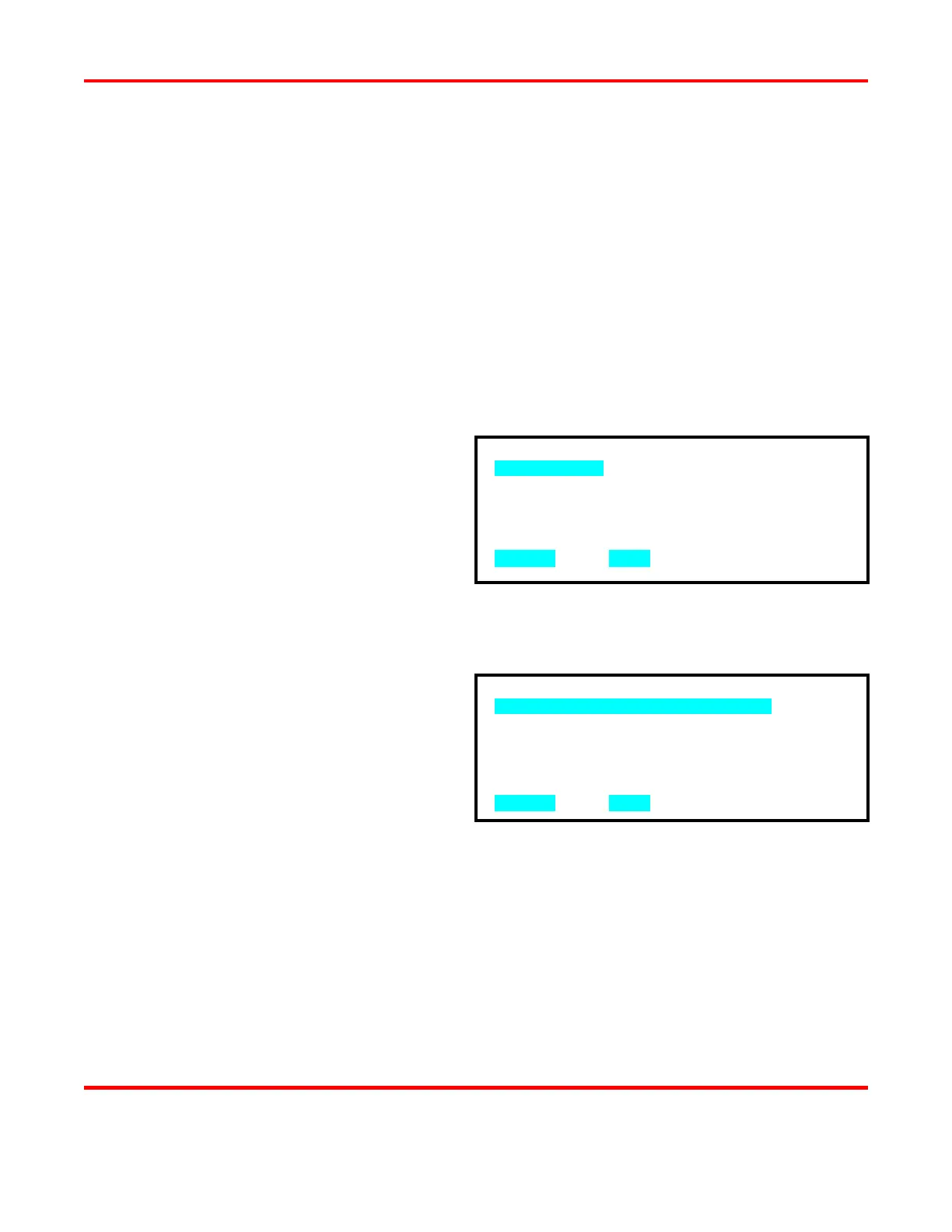
2 Press 4 for the INPUT SWITCH
SELECT menu.
Mechanical Selection
This selection accepts dry contact, single, or double pole switch or reed relay devices. This is the
factory default setting and will run AMADA WELD TECH weld heads.
1 From the INPUT SWITCH SELECT
menu, press 1 for the mechanical switch
select menu.
2 Press the 1 or 2 key to select how the
input mechanical switches will initiate
the Power Supply. The display
automatically returns to the SETUP 1
menu.
• Mechanical Switch Normal Open: Initiate the Power Supply by closing the mechanical
switches.
• Mechanical Switch Normal Closed: Initiate the Power Supply by opening the
mechanical switches
NOTE: You will get an INPUT SWITCH ALARM unless you close the Firing Switch
and Foot Switch inputs before selecting the Normal Closed option.
1. MECHANICAL
2. OPTO
3. PLC
NUMBER Select, MENU Previous menu
1. MECHANICAL SWITCH NORMAL OPEN
2. MECHANICAL SWITCH NORMAL CLOSED
NUMBER Select, MENU Previous menu