CHAPTER 1: DESCRIPTION
UB25 LINEAR DC RESISTANCE WELDING CONTROL
990-665 1-3
Section II. Description
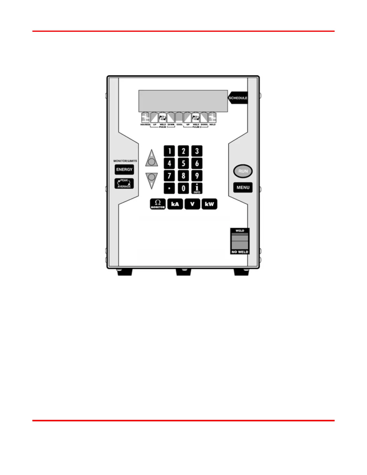
UB25 Front Panel
The front panel contains all the controls and indicators necessary to operate the Power Supply. You can
program the Power Supply using the data input keys and information appearing in the Liquid Crystal
Display (LCD). Descriptions for each button and display are in Section IV of this chapter, Controls and
Indicators.
All electrical connectors, data connectors, and the ON / OFF switch are located on the rear panel of the
Power Supply. Connection instructions are described in Chapter 2, Getting Started.
Complete technical specifications for the Power Supply are listed in Appendix A, Technical Specifications.
Connector pin identification and specifications are listed in Appendix B, Electrical and Data Connectors.