CHAPTER 5: SETUP SOFTWARE
UB25 LINEAR DC RESISTANCE WELDING CONTROL
5-12 990-665
Control Signals Select
This option selects the type of external switch to be used by the Schedule Selection, Process Inhibit,
and ISTOP inputs and how these switches are activated.
1 From the SETUP 1 menu, press 5 for
the CONTROL SIGNALS SELECT
menu.
2 Follow the INPUT SWITCH SELECT
instructions on the previous two pages,
the procedures are identical for
CONTROL SIGNALS SELECT.
3 Press MENU to return to the MAIN MENU.
Weld Counter Functions
1 From the MAIN MENU, press the 2 key.
This will bring up the WELD
COUNTERS screen. Use steps 2
through 5 below to reset each counter.
2 Press the 1, 2, 3 or 4 key to select the
desired weld counter.
NOTE: The example to the right shows
the TOTAL WELDS screen.
3 To reset the counter, press 0 on the
numeric keypad. To input a preset
number, use the numeric keypad.
NOTE: If you accidentally reset the wrong counter, press the . (period/decimal point) key. The
original count will reappear.
4 Press the MENU key to return to the WELD COUNTERS screen.
5 When all counters have been reset, press the MENU key to return to the MAIN MENU.
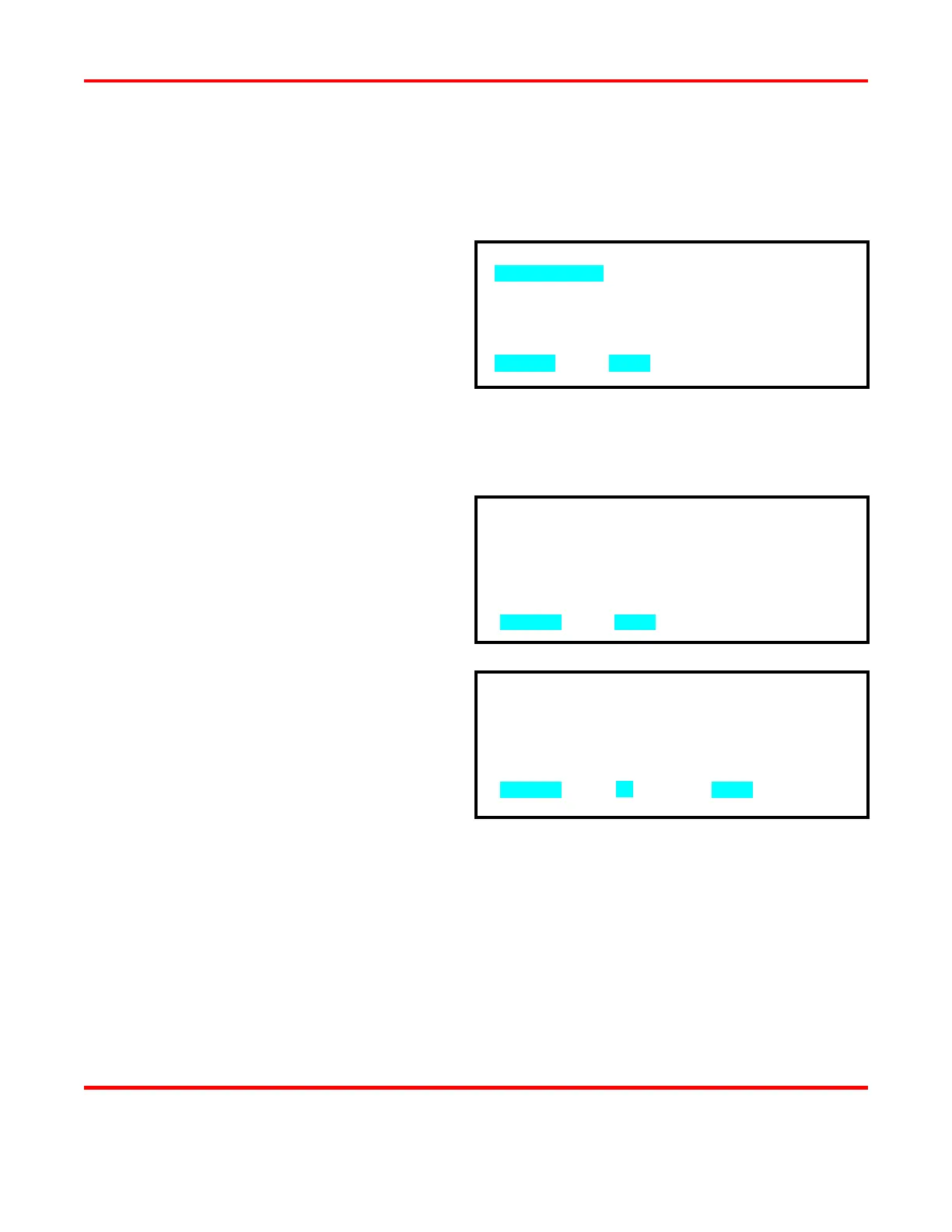
1. TOTAL WELDS : 0000000
2. OUT OF LIMITS HIGH : 0000000
3. OUT LIMITS LOW : 0000000
4. WITHIN LIMITS : 0000000
NUMBER Select, MENU Previous Menu
1. MECHANICAL
2. OPTO
3. PLC
NUMBER Select, MENU Previous menu
TOTAL WELDS : 0017429
NUMBER Change, Restore, MENU Menu