CHAPTER 7. CALIBRATION
UB25 LINEAR DC RESISTANCE WELDING CONTROL
7-4 990-665
Section III. Calibration Procedure
1 Verify that the equipment is connected as shown in Calibration Setup.
2 Turn the Power Supply ON.
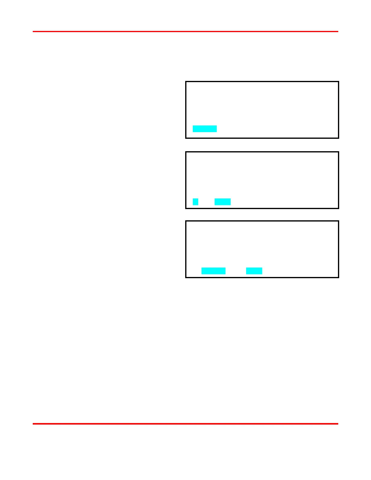
3 Press the MENU key to bring up the
MAIN MENU screen.
4 Press the 7
CALIBRATION.
5 From the first calibration screen, press
the keypad ▼ (down) key to the PRE-
CALIBRATION screen.
6 From the PRE-CALIBRATION screen,
press the 3 key to RESET
CALIBRATION before performing the
following procedures.
7 At the screen prompt, press the 2 key for
YES to confirm that you want to reset
8 From the PRE-CALIBRATION screen, press the 2 key to start the sequence of on-screen
calibration instructions.
9 The next screen is CALIBRATION SHUNT which requires you to enter the actual value of the
4,000 micro-ohm shunt (the value is printed on the exterior of the shunt). Enter the value using
the numeric keypad, then go to the next screen.
NOTE: The prompts at the bottom of the screen that tell you how to go to the next screen may
vary from screen to screen. To go to the next screen, press the key indicated by the prompt.
10 Follow the instructions on the calibration screens. Each screen will show you the desired energy
output value for that calibration step. Use the oscilloscope to measure the output, then use the
▲▼ keys to adjust the Power Supply output to the correct average value.
0. WAVEFORM CHECK 5. COMMUNICATION
1. SETUP 6. RELAY
2. WELD COUNTER 7. CALIBRATION
3. COPY A SCHEDULE 8. RESET DEFAULTS?
4. SYSTEM SECURITY 9. CHAIN SCHEDULES
NUMBER Select an item
CALIBRATION SHOULD BE PERFORMED BY A
QUALIFIED TECHNICIAN ONLY.
REFER TO MANUAL FOR CALIBRATION SETUP.
1. TEST UB25 (T-232 REQUIRED)
2. CALIBRATE UB25
3. RESET CALIBRATION
4. TEST SERIAL PORT
▼NUMBER Select, MENU Previous menu