CHAPTER 4: OPERATING INSTRUCTIONS
UB25 LINEAR DC RESISTANCE WELDING CONTROL
990-665 4-7
Section IV. Programming the Weld Monitor
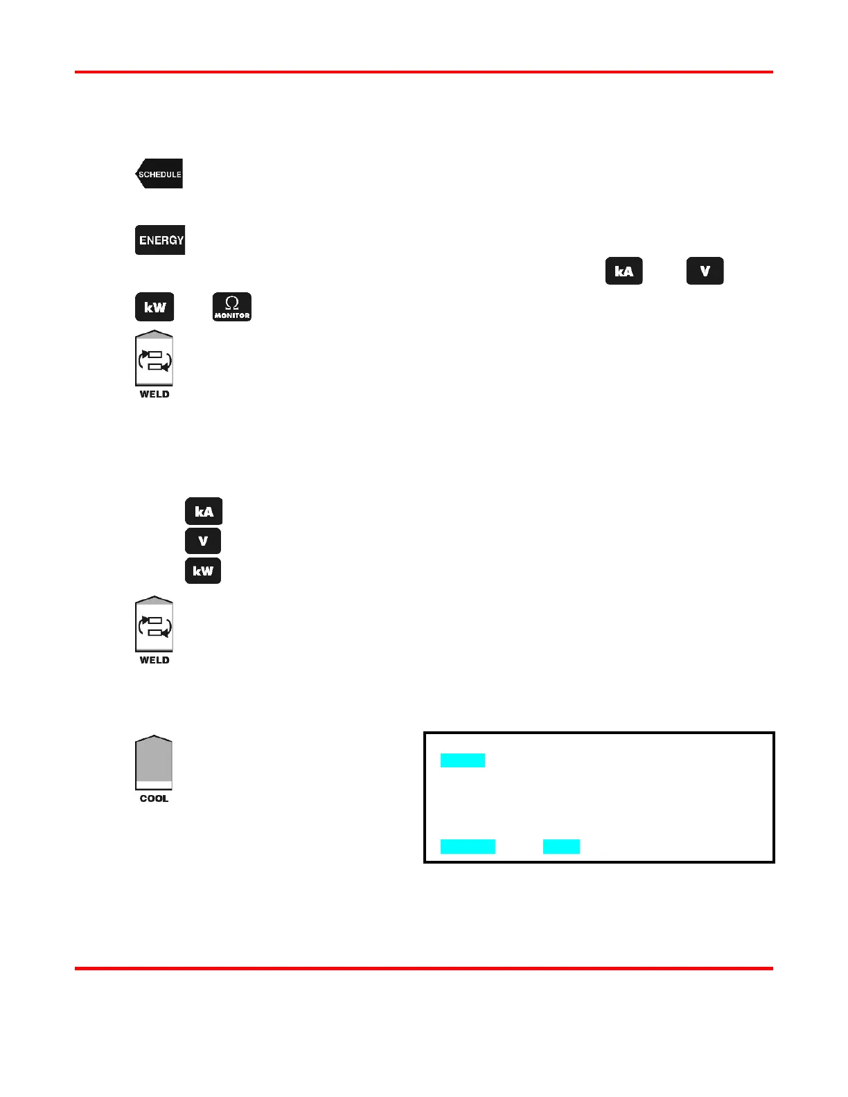
Press the SCHEDULE button, then select a Weld Schedule using either the ▲▼
arrows or
the numeric keypad. Fire the welder and view the output waveform (shaded
graph) on the display.
Press the ENERGY key to access the MONITOR screen.
rform a weld and view the trace of the weld parameter, use the
or
key to view the desired waveform.
Toggle the Pulse 1 weld time/energy selector key to select the upper limit field for the
weld period. Use the numeric keypad or the ▲▼ arrows to enter the upper limit
for the Pulse 1 weld period. The Power Supply can monitor:
Current from 0
1.2 kiloamps.
Voltage from 0
6.5 volts.
Power from 0
8.0 kilowatts.
Perform one of the following to program the Pulse 1 monitor limit mode:
Press the kA key to program current as the limit mode.
Press the V key to program voltage as the limit mode.
Press the kW key to program power as the limit mode.
Toggle the Pulse 1 weld time/energy selector key to select the lower limit field for the
weld period. Enter the lower limit value for the Pulse 1 weld period.
NOTE: In order for a Pulse 1 lower limit to be programmed, you must first
Pulse 1 upslope in the weld schedule.
The lower limit mode (current, voltage, or power) will automatically be the same as the
upper limit mode programmed in Step 5.
Press the COOL weld period key.
This will bring up the PULSE 1
OUT OF LIMITS ACTION screen.
This screen allows you to select the
action that the Power Supply will
take if the Pulse 1 upper or lower
limits are exceeded. You have four
•
NONE takes no action if upper or lower energy limits are exceeded.
PULSE 1 OUT OF LIMITS ACTION
1. none
2. STOP DURING PULSE 1
3. INHIBIT PULSE 2
4. APC: STOP PULSE 1/ALLOW PULSE 2
NUMBER Select, MENU Previous menu