CHAPTER 4: OPERATING INSTRUCTIONS
UB25 LINEAR DC RESISTANCE WELDING CONTROL
4-8 990-665
• STOP DURING PULSE 1 stops the weld immediately during Pulse 1
, and prevents
Pulse 2 from firing (if applicable).
• INHIBIT PULSE 2 stops the weld at the end of Pulse 1, and prevents Pulse 2
from
firing. This function will not operate if both pulses are joined without a cool time.
• APC: STOP PULSE 1/ALLOW PULSE 2 stops Pulse 1 immedia
or lower energy limits are exceeded, but allows Pulse 2 to fire
not operate if both pulses are joined without a cool time.
NOTE: See "Active Part Conditioner" in Chapter 3.
After making your selection the display will automatically return to the monitor screen.
Program the upper and lower limits for Pulse 2 by repeating Steps 4 through 6 above using the
keys for
Pulse 2, entering appropriate values for Pulse 2.
The monitor limit mode (current, voltage, or
power) for Pulse 2 can be different than
the monitor limit mode for Pulse 1.
Press the HOLD period key. This
will bring up the PULSE 2 OUT OF
LIMITS ACTION screen.
This screen allows you to select the
action that the Power Supply will
take if the Pulse 2 upper or lower
limits are exceeded. You have two
choices:
• NONE takes no action if upper or lower energy limits are exceeded.
• STOP DURING PULSE 2 stops PULSE 2 immediately after upper or lower
energy limits are exceeded.
After you have made your selection the
display will automatically return to the
MONITOR
screen.
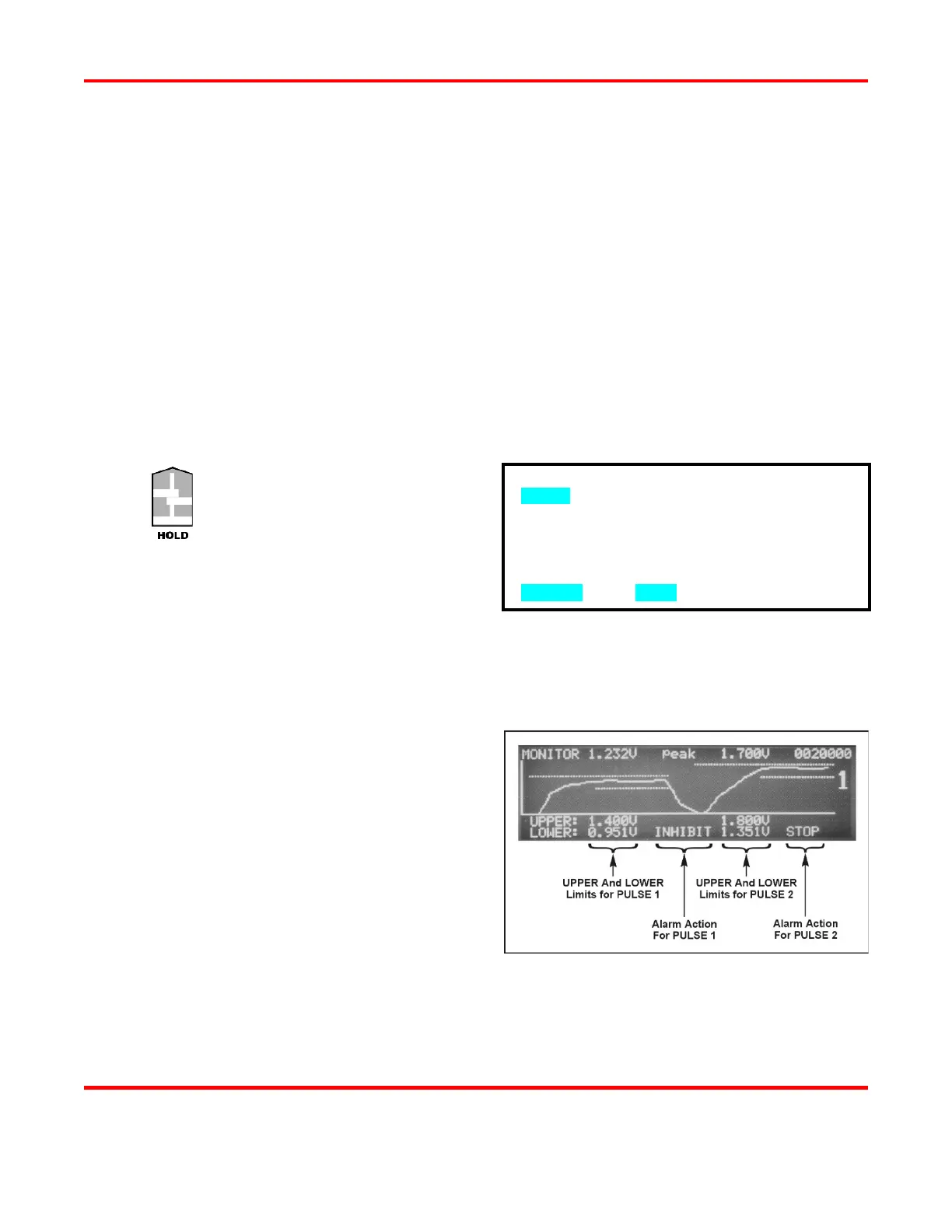
: The Power Supply adds dotted lines
to the appropriate graph to show the
programmed limits
.
The screen on the right shows how the
Limits
and Alarm actions appear when an
actual weld trace is displayed on the LCD.
: All lower limits apply only to the Pulse 1 and Pulse 2 WELD
periods. Lower limits do
not
cover any upslope or downslope periods. All upper limits apply to the entire Pulse 1
periods, including their upslope and downslope periods.
PULSE 2 OUT OF LIMITS ACTION
1. none
2. STOP DURING PULSE 2
NUMBER Select, MENU Previous menu