APPENDIX D: DEFINING THE OPTIMUM PROCESS
UB25 LINEAR DC RESISTANCE WELDING CONTROL
D-4 990-665
• Group II – Resistive Metals
− It is easier to generate heat and trap heat at the interface of resistive metals and therefore it
is possible to form both solid state and fusion welds depending on the time and temperature.
Upslope can reduce contact resistances and provide heating in the bulk material resistance.
• Group III – Refractory Metals
− Refractory metals have very high melting points and excess heating can cause micro-
structural damage. A solid-state joint is therefore preferred.
The chart below gives some guidance on the type of joint that can be expected and design considerations
required when joining materials from the different groups.
Group I
(Copper)
Solid-State
• W/Mo electrodes
Solid-State
• Projection on Group I
Solid-State
• Fine projections on
Group III
Group II
(Steel)
Solid-State or Fusion
Solid-state or braze of II
on III
• Projection on III
Group III
• Solid-State
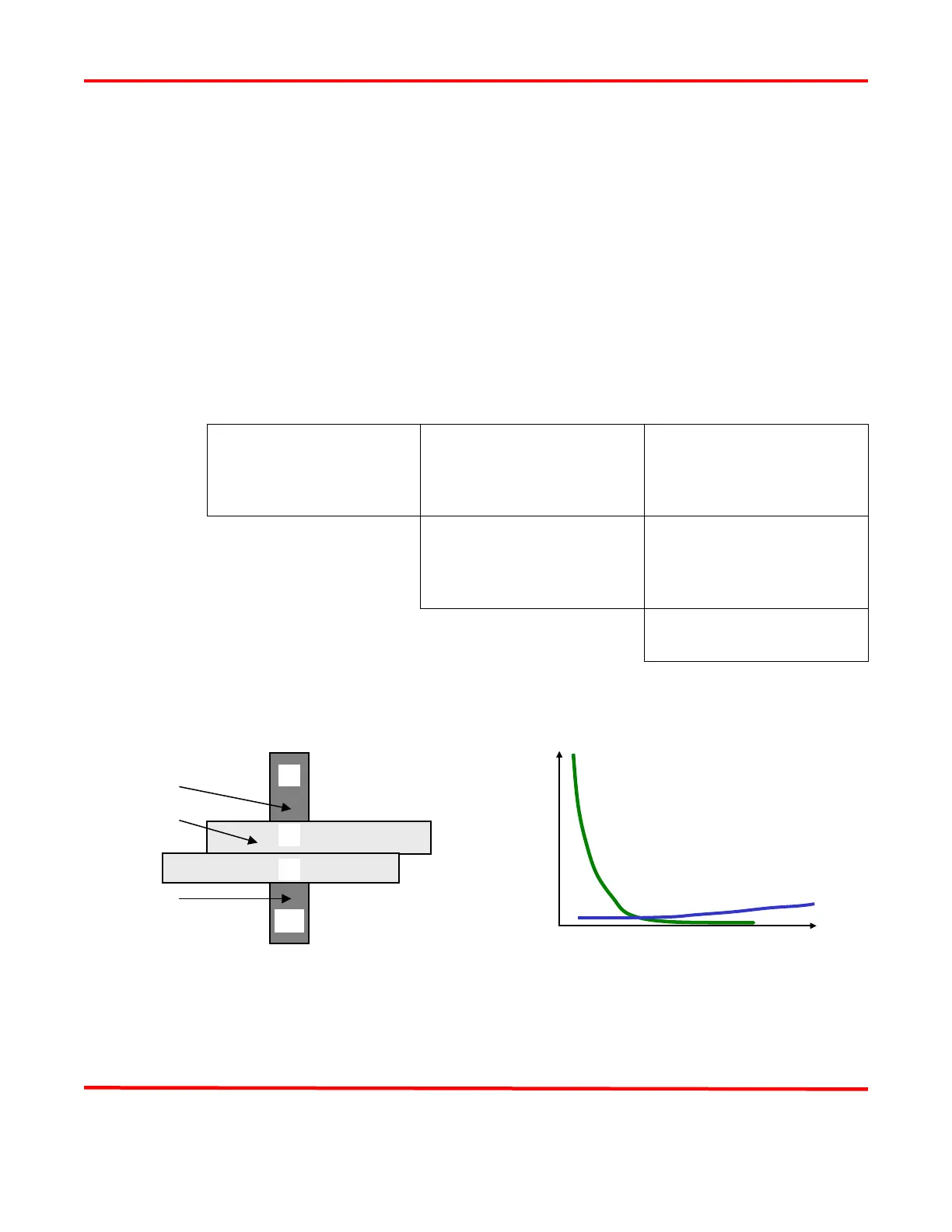
Basic Principles
The figure above shows the key resistances in a typical opposed resistance weld and the relationship
between contact resistances and bulk resistances over time, during a typical resistance weld.