Controller / User Interface | 4-37
Output Setup
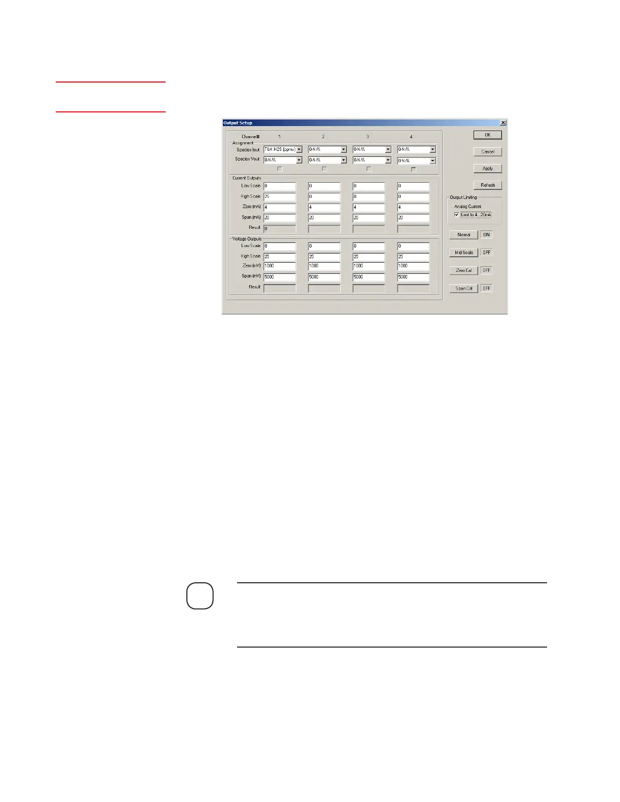
The Output Setup dialog box contains current and voltage output assign-
ments plus concentration alarms and setting parameters.
There are four independent isolated 4–20 mA
DC
outputs (see Figure 3-4,
Customer Connections, I/O Board) that can be either loop-powered (loop
supply by customer) or self-powered.
There are also four 1000–5000 mV
DC
outputs. The default signal assign-
ment is configured to meet the specifications of the end user. If either the
current or voltage output assignments need to be changed, click the drop-
down arrow beside the output and select a different assignment.
The default signal assignment is configured to meet end user specifica-
tions. To change current or voltage output assignments, select an option
from the Assignment list.
In addition to the usual capability of zeroing and spanning the V/I and
Voltage Outputs, you can also set them to a mid-scale level for diagnostic
purposes. The low end of each analog output range can be a nonzero value.
If the system is set up for a two-stream configuration, the prefixes
“A” and “B” will precede the species name under Species Iout and
Species Vout (Figure 4-13). If the system is set up for a single-stream
configuration, these prefixes are not shown here.
Channel# (1, 2, 3, 4) lists various parameters for each of the four analog
output channels.
Setup (tab)Output
Figure 4-13.
Output Setup dialog
box.
NOTE
 Loading...


