Controller / User Interface | 4-11
To set up Modbus Serial or TCP parameters to allow communication be-
tween the analyzer and Configurator Software:
Hazardous Locations
Before proceeding, test the area around the analyzer for explosive
gases and proceed only when the area is found to be safe.
Do not remove the cover of the Explosion-Proof Digital Communica-
tions Port on the front of the Lower Enclosure, do not connect a serial
cable to the Communications Port, do not open the Upper/Lower En-
closures, and do not power up/down the analyzer or computer if there
is an explosive gas atmosphere present.
Modbus Serial / Modbus TCP Communication Setup
The PC can communicate with the analyzer through the Local Service
Port or the Remote Service Port, but not both at the same time. The Local
Service Port (RS-232) is located on the front of the Lower Enclosure; the
Remote Service Port (RS-485) is accessed via connector J303 on the Host
Controller board. See also “Digital Communication” in Chapter 3.
!
CAUTION
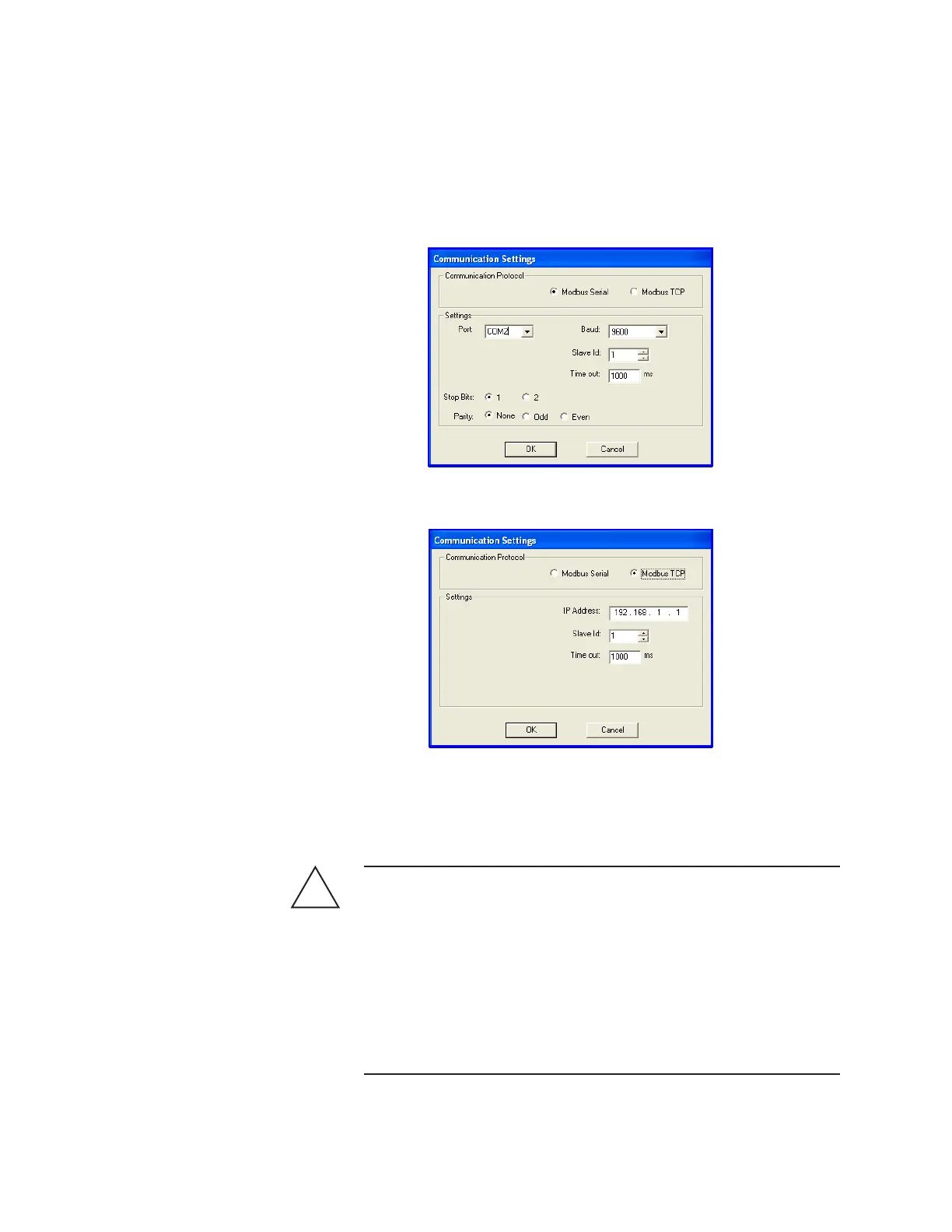
Figure 4-2.
Communication
Settings dialog box
(Modbus Serial
communication).
Figure 4-3.
Communication
Settings dialog box
(Modbus TCP
communication).
 Loading...


